Search This Blog

Friday, May 20, 2016

Simple Desk Design. Tenon Array Joint.

My local Menards store had 1.5" thick butcher block birch counter/bench tops on sale recently.  I needed a new desk to replace a plastic topped desk that I use as a computer desk.  The plastic top rests on a metal tube base, but has started to sag and crack under the weight and heat from my PC.

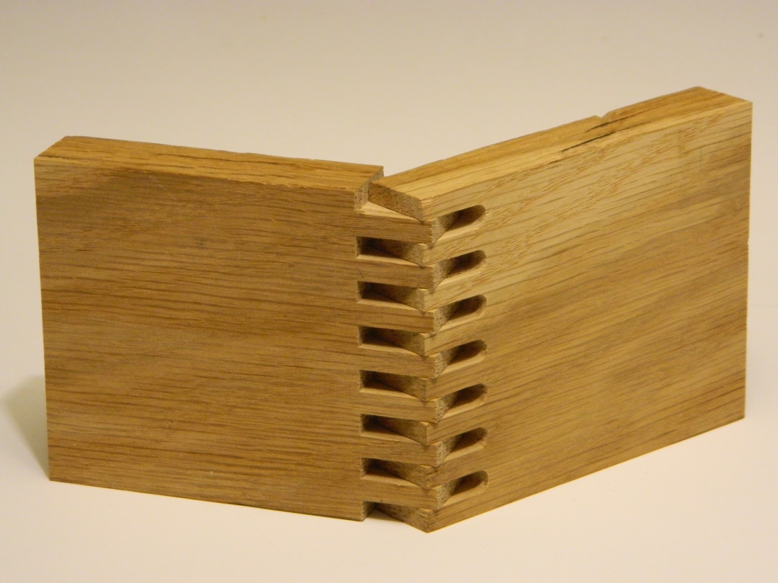
I previously came up with a tenon array joint that makes a great connection between legs ends and table tops. The 1.5" thick hardwood is plenty thick for a good joint. All I would need would be something with a little cross sectional area to use for legs to support it. No stretchers required.

I've used cedar 4x4 posts in the past as legs for shop benches and my CNC cart.  With a little picking through of what was available I found some straight and clear 8' cedar 4x4s to use.

I wanted my desk to be 29" to the top when done.   I cut 4 leg sections roughly 28.5" long to allow for 1 inch tenons to penetrate the top.
   My CNC just barely had the capacity to hold the 48" x 25" top.  I used it as shown to cut the four mortise arrays each centered 1/5 of the length and width from the edges of the top.
The legs were first cut at a compound angle to tilt 4 degrees in the long direction and 2 degrees in the short direction.  Then I clamped them into my compound angle clamping rig and cut the tenon arrays with the CNC.  I made the tenons .004" smaller than the mortises for a slip fit and some room for glue.

I left the top clamped to the CNC while I tested the fit of the joints. I made a mistake when cutting the end on one of the legs, so I had to recut it a little shorter.   The tenons ended up .75" long and the mortises I cut .8" deep.  The legs slipped in with just a little wiggling back and forth. They come out using the same technique.

 If the legs would not have fit easily I could revise the CNC file for the mortises and recut them a little larger.   I didn't need to in this case.  All legs fit fine.

I haven't glued the legs in yet.  They need some sanding and finish, which will be easier with them detached from the top.  The outward flare of the legs give the desk a more solid stance, with less tendency to rack or twist than if they were vertical and all parallel.
The 3.5" x 3.5" mass of the legs has room for and begs a more interesting profile.   In use though I'll never see these legs. The birch top will look great with some clear finish on it.   I may paint the legs white or black to make a less distracting setting for the top.

I used my CNC to chamfer the bottom of the legs. With the bottom plane at a compound angle each corner bevel is slightly different.  A little hard to see in the photo below as most of the 1/2" chamfer sinks into the carpet.  The chamfer should keep the leg bottoms from getting snagged/worn as the table is moved/scooted around.


4D

Monday, May 16, 2016

Improved Light Bracket for my Overhead Camera Rig

My first light bracket design hasn't failed. That I can perceive how they would fail has moved me to come up with a new design that eliminates the weaknesses of the first. This is not an uncommon happening as I work through the design of a thing. 

Making the first prototype is more about being able to discover where an idea might be weak than being done with the design.


This version was cut from the same scrap of red oak as the first two were. I removed much of the initial potential mass in the first design. This version removes only the outer bevel where no forces would pass through. The beveled edge was cut with a 3/16" end mill using the fluting toolpath that is available in Vectric's Aspire software.  The side hole was drilled out with a #7 drill bit then tapped for 1/4-20 threads.


The center cone spreads force from the screw head across the bottom area against the rig post.  The side bolt simply threads into the initial mass for strength.


The lights now do a great job of illuminating whatever I want to make a close-up photograph or  video of.  Next for this camera rig I'm working on an improved camera hanger bracket.   So far I'm not satisfied with my first or second ideas. The second idea is shown in the last photo above. It worked, but not as well as I hoped it would.   That tells me there is a better solution out there.  Now just to find it.

4D


Friday, May 13, 2016

Light Bracket for my Overhead Camera Rig

This was a quick project to allow me to mount my LED lights directly onto the posts of my overhead camera rig.

The LED lights came with a short tripod base, but by unscrewing the lamp module from the base I realized they could be mounted on my camera rig. I just needed a bracket that would allow me to adjust the angle and direction they pointed at.  This is the solution I came up with:


Carved from a scrap of red oak using my CNC.


The center hole is 1/4" diameter for a 1/4" bolt.


The side hole was drilled with a #7 drill bit and tapped for 1/4-20 threads.


Each post was drilled and tapped for 1/4-20 bolts.


Friction between the bracket and post keeps the light from rotating when the bolt is tight.


Angle of the light can be adjusted by loosening the knurled handle.


 I will seal these brackets with tung oil to prolong their lifespan, and slow down any tendency to expand or contract. For the moment they seem strong enough, but the drier the oak becomes the greater chance it may split under the load of the lamp.

4D


Creative CNC Joinery, and Other CNC-Cut Solutions.

My furniture design students often came up with designs/parts that looked difficult or impossible to build.  We have 3 CNCs now in the design workshop, and two of them have been modified to allow CNC cuts on boards mounted vertically or at an angle or compound angle. When you are released from the limitations of flat cutting a world of potential is revealed. What seems impossible or difficult to make at first often becomes possible with a little sketching, drafting, jig design, experimentation, determination, and innovative tool path creation.

It is important to understand the structural properties of the materials used when trying out an original joint or cutout.  Grain direction, wood expansion and contraction, dryness, natural flaws, stiffness, flexibility, and tendency to split, are just a few of the things to consider.

Some examples of the original CNC-cuts solutions I've come up with:


Three-way center interlock:


We have our advanced students design and build a 3-legged (or fewer legs) stool during the first two weeks of class. When 3 legs need to be connected with a stretcher there are only a few options.  You can run stretchers from leg to leg around the perimeter. You can bring stretchers to the middle, pin wheeling them to each touch the other two. You could bring them into a center hub piece. The simplest way at first could bring them to meet at the very center, except there is only a small area of intersection you can make a 3-way joint within.  A 3-layer "stack" would work, but removes 2/3 the thickness off each stretcher, and leaves the center piece needing to be cut on both sides or from the top.  My 3-way interlock maximizes glue surface area, maintains through-grain structure. vertical stiffness, and still locks the three elements together within that small area. You cut the same profile on the ends of each piece from the top. This pattern can be scaled up or down to match the width of your stretchers, and is only limited in height, diameter, or by the length of the bit you'll use to cut it. One application for it:  
3 on 3, connected with a center bolt.

Angled through-scarf-lap joint:


Often a project requires one board to appear to pass through another. If the same size they can be half-lapped. If a smaller piece is at the edge of a larger piece you can still interlock both with cuts into their edges.  When a small board penetrates the center of a wider board the options are limited. Cut the through board and pass a dowel through the larger piece into these cut ends. Or half-lap the through board inside a hole cut through the wide board.  You could make short tenons on each cut end and mortise them half way into the wider board.  

The result from all of these options is a joint that is weaker than the original strength of the through piece.  My angled through scarf lap joint maximizes side grain glue surface, maintains strength at the ends of each half, and is invisible once glued together. Sloped halves meet inside the joint. This sloped intersection wedges out as the parts are clamped in, leaving them very tight inside the hole.

Compound angle mortise and tenons:

In chair frame design a potentially more interesting and inviting solution can be found by flaring the sides out, wider in plan view at the front than the back. A more stable footprint can be found by flaring the legs out, wider in front view at the bottom than at their tops. The challenge this creates is that now any structural connections (stretchers) between the two sides would meet the sides at a compound angle. By first cutting the extended (by the length of the tenon) end of each stretcher parallel to the face of the side it will intersect, and then clamping that stretcher on the CNC so that compound end is perpendicular to the CNC bit, we can cut a standard tenon to go 90 degrees into the angled sides, at the compound angle relative to the stretcher required.

Half blind mitered dovetailed corners:

This half blind dovetail example was a request from a student in my CNC focused furniture joinery class.  He had found a photo example online, and as far as my research got it looked as though you could use a jig on the router table to cut half of this joint, but the other half would need to be hand cut. The CNC solution came to me one night and required making a jig to hold his panels under the CNC at 45 degrees, and once we had that we could cut both halves of a slight variation that looks exactly like the original example.  This joint can also be cut for 72 degree (5 sides) and 60 degree (6 sides) corners. I made a 5-sided box with the dovetails laid out to spell my name in Morse code just to inspire the students.

Creative through-finger joints:
Triangular pins.  Walnut centers.

Pseudo Dovetails
Once you are able to cut vertically on a CNC an obvious joint to make is the box joint. But now that you can make box joints with the precision and control of a CNC, the different sizes of router bits available present options for amazing creativity in the shape of the interlocking fingers. A pattern drawn for the positive side of a joint can be used with only a little modification to make the negative pattern for other side. The round shape of each bit and length of the cutting edge are the only limitation, but results can be as varied as your name in through-fingers, Morse code in dots and dashes as through fingers, or geometric patterns or progressions as through fingers.


Finger (box) and dovetail joints on other than 90 degree corners.

It is rare to see a 5-sided (or 3 or 6 or 7 sided) box in an internet search for wood boxes. Why?  Most woodworking equipment is set up to work at 90 degrees. Four 90-degree corners make a 4-sided box.  In furniture design a 100 degree or 105 degree angle between chair frame parts might be more interesting than 90 degrees, but traditional methods of creating joinery at those odd angles limits their use.  To make fingers on a 5-sided box each end needs to be cut at 72 degrees. An angle jig (set at 18 degrees) on the CNC will let you clamp these sides under the bit so their 72 degree end is perpendicular to it.  The same strategy can be used for more complicated joinery on non-90 degree corners, however some joints may need clamping ends at two different angles.

Of course, a CNC's precision can always make perfectly centered "ordinary" finger joints no matter the width of the board used
.


Pin Joints.  These examples are an experimental set of fairly conventional joints, with the added strength from fingers/pins cut in the end grain of one part to pierce the other part of the joint.

Reinforced with 3 finger tenons.

Angle intersect...

A simple butt joint?

Not so simple.  4 x 5 end grain pin array.
Pins add a great deal of glue surface area for these joints. They are difficult to pull apart without glue. With glue the wood around the joint would fail before the joint does.
Simple rabbet?

2 x 5 pin array hidden inside.
Shoulder Rabbet.
Back side:Shouldered rabbet.
Hidden end-grain pins.
Pins full depth of joint.


Through Pins.  Endgrain should pop with finish. 

Hidden (blind) finger row on 45 degree board intersection.  Fingers cut in end grain don't always have to be on the ends of the two boards that are being joined.  When one board has to intersect the middle of another board a row of tenons into matching slots will still be a strong joint.  When the boards don't meet at 90 degrees an angle clamping fixture can still help cut a working solution.


An alternative to the 45 degree joint above, with a slightly different look would be this triple tenon version:
Slot half was cut while clamped at 45 degrees.  Tenon half was clamped vertically.


Predetermined alignment of cutouts on bending plywood laminations.  Curved parts can be made by gluing together layers of thin wood or bending plywood around a form.  If the part has cutouts they can be difficult to cut after being curved. With the CNC these layers can be individually cut to include the cutout, with each layer slightly different than the others to accounts for their position in the stack.  One good example is this aquarium stand.  Inner layers are shorter than outer layers, so we reduced each layer by a fractional amount so that the holes would only line up after being clamped around the form. Extra holes were added for pins to keep the parts aligned while the glue dried.


Tapered sliding dovetails, positive and negative halves.   The angle, width, and length of most dovetail bits can be found on the packaging they come in, or etched on the bits themselves.  Knowing this it is possible to lay out a single depth tool path to run that dovetail bit down a tapering path to cut the slot in a board's face and both sides of the projecting dovetail on another board's edge or end. The plunge for a dovetail bit usually starts outside of the board.  Slots are best cleared out with a pocketing straight bit before the dovetail bit undercuts the sloped sides. Blind slots can be cut with the path line entering then doubling back.  A small degree of taper down the length of the dovetail slot lets the joint slide in easily yet lock very tight once fully inserted.

Angled slices through cylindrical shapes as they turn on a rotary axis.  A sine wave pattern was necessary to have the router cut what appears to be a straight 30 degree slice through these cylinders.

Sine wave pattern used to cut recess for aluminum.

Ramping dovetails.  When two boards meet at a low angle to each other, such as the a-frame sides on this cart, you only have a few options on how to connect them using just the initial mass of each piece.  You could butt-glue them edge to edge, but the standing V wants to do the splits and may still split this joint apart.   Looking at how much they overlap before being mitered a single option remains for a joint that will increase glue surface area and interlock the two halves.  You can cut a dovetail slot in one side and leave a dovetail tongue on the other. These will ramp together, locking the two halves when flush at the top.

Mitered corners with splines.  This example needed a little cleanup with a 1/8" chisel to remove the fillets left by the round 1/8" bit.  The opposing splines help when gluing this joint together as they keep the mitered faces from sliding apart under clamping pressure.


Construction Lumber Joinery.  These examples show how a building (Tiny House in my case) could be put together using CNC-cut joinery rather than nails.


The joinery options shown and described here just scratch the surface of what is possible when you can clamp parts vertically or at any angle/compound angle under a 3-axis CNC.

The rig I use to clamp parts vertically or at any angle is described here.

Comments and questions are welcomed.
4D