Search This Blog

Sunday, January 29, 2023

Making a Square Table Top From a Rectangular Butcherblock Countertop.

I enjoy using wood for my projects.  If the shape or thickness of a board is not what I need then I can usually reconfigure the wood to make it into what I need for a project. 

This post is about dividing a 25" x 48" x 1.5" butcherblock panel so that the parts can be reassembled into the largest possible square. A little iterative drafting and some easy math is all that is needed.

Math comes in handy to calculate how much area the butcherblock panel has, and with allowance for the kerf cuts to divide it what will be the largest square that can be made with that same area.

Multiply 25 x 48 to get  1200sq.in.. If no material was lost when dividing the butcherblock then the largest possible square would have sides that are the square root of 1200 or 34.61". 

My CNC software has a handy tool for measuring the area within any outline. I'll use a 1/4" diameter router bit to cut the butcherblock into 3 pieces.  The length of those cuts times 0.25" will be the area lost from kerf cuts. Subtract the kerf cut areas from 1200 to find the final maximum size of the square that can be made. 

These are the two lines I cut to divide the rectangular butcherblock panel. 

Subdivided panel.
After being cut the parts are put back together to make a 34.45" x 34.45" square. 

Reassembled Square
This table top will be mounted to a red oak base I made. Two inch thick legs with stretchers that pinwheel and bolt to each other. I'll attach the base to the top with crazy 8 connectors. 

Of course reality comes into play when actually making the parts.   This butcherblock panel claimed it was 25" x 48", but it was 1/8" narrower.  It also came with edges that had been rounded over.  When the small triangle piece moves to its position in the square its bottom rounded edge meets the top rounded edge of the large piece, Trimming those edges to get past the round over shifts the small triangle in, losing about 3/8" of length as it tucks into the corner.   The final "square" will now be 3/8" smaller in one dimension. 

To start I could have ripped off 1/8" of both the left and right side of the initial board, and recalculated the  geometry to make a slightly smaller square from a narrower starting board.  This butcher block panel is roughly 80lbs of wood.  It was a challenge to lift up and place on my CNC.  In place it doesn't slide without a significant effort.  To run it twice through my table saw would have been far more work.  

To clamp the 3 boards together as a square I used 4 long parallel bar clamps. Two laid down in one direction and the other two over those to keep the triangles aligned and in place. 

Reconfiguring rectangles of most lengths and widths is possible.  You start by making sure your starting and ending areas are the same. Subtract the area for kerf cuts you have to make, and verify that the board you start with is actually the dimensions you used for your calculations. In "Mathematical Puzzles & Diversions" by Martin Gardner (Amazon link) it shows how to cut an equilateral triangle into 4 pieces that can rotate around to make a  square. Some day, maybe, I'll make a triangle from this now-square table top. ;) 

Questions are encouraged!
4D
  

Thursday, January 12, 2023

Adventure Cutting Aluminum with my CNC

This is my tale of trying to cut some 6061 aluminum to make an aluminum version of a push button depth stop for my Wen benchtop drill press. 

I bought a 4" x 6" x 3/4" thick piece of 6061 aluminum from Amazon. From this I cut the body of the depth stop.  I also have a 5/8" diameter rod of aluminum I used to make the button for the depth stop from.  

Some web research found recommendations for feed speed (17-24rpm), plunge speed (6"/minute), depth/pass (0.03") and bit RPM (13,000) to use when cutting aluminum.  My CNC uses a variable speed Dewalt router that can be set at the recommended speed. The other variables I can set for each toolpath in the CNC software I use (Aspire from Vectric.com). 

My first try was to cut the perimeter and center hole of the press button body from the 4" x 6" block.  I set up the job to cut the part near one corner of the block. The bit I used was a 3/16" spiral upcut end mill.  Two sides of the cut were 1/2 the bit width from the edge. The other 2 sides were full width cuts through the aluminum block.  I thought all was going fine until about halfway through the aluminum. At that point I started hearing more chatter from the bit as it made the full width cuts through the block.  With 1/8" or so to go the chatter was so bad that I had to stop the cut.  I took the block off the CNC, then cut the part free from the block using my band saw.  I then used a spiral flush trim bit on my router table to trim off the remaining aluminum from the bottom edge. I held the part with a c-clamp as I fed it through the flush trim bit.  The bit speed was also turned down to about 13,000rpm. 
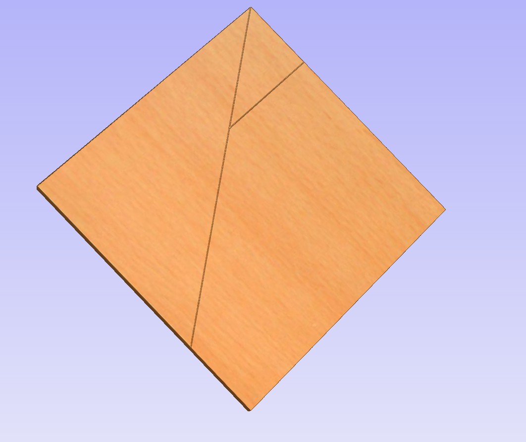
First attempt
With the part free from the CNC I could see the affect of the bit chatter on the revealed side. Measuring it with a digital caliper it was close to 1/32" too small in both X and Y direction. the center hole was also not centered between the sides as it should have been.  The deflection from the full width passes was clear.  

With a night to contemplate what had happened I decided to try again the next day. It had been full width passes and ramping down that my CNC had trouble with. The conventional profile cuts had deflected toward the part.  

For my second attempt I started with a block only 1/8" larger than the final part. I rough cut out the body block from a machined corner of the original block using my bandsaw.  

No perimeter passes would be full width.  To avoid having to ramp into pocket cuts for the center hole I pre-drilled a 1/4"d hole (using my drill press) through where the pocket was to be cut. 

Holding the block in place for the cuts started with a t-track bolt up through that 1/4" hole.  A lock washer under a nylock hex nut held the block down tight to my spoil board. To make sure the CNC cuts didn't spin the block while cutting it I separated the cuts into unique toolpaths for each side. While any side was being cut I clamped a block against the opposite side. All profile toolpaths were climb cuts, and only through 1/16" off each side. Twenty two steps were used to get through the 3/4" thick block. All cuts were climb cuts so that any deflection would be away from the part rather than toward the part. 

Once the perimeter was cut I took it off the CNC.  Now I could clamp the part in my low profile vise to cut the center hole. Starting each pass in the center 1/4" hole I had no need to ramp down between passes.   When done I again measured the part and found it to be within .01" of the intended size. The hole was perfectly centered as it was supposed to be. 

Part with hole in top and side. 
Next came cutting the elliptical hole in the side for the button.  I again used a smaller drill bit to drill an opening in the center. With the part clamped side up in my low profile vise I used profile cuts on-the-line to start in the opening before cutting around the perimeter of the elliptical hole. 22 passes again for roughly .75" of depth.  The elliptical hole measured exactly the intended 1/2" x 5/8". In the bottom of the elliptical hole a smaller round pocket was cut for the conical spring. 
Conical Springs.
With all the holes in the depth stop body complete, my attention turned to making the elliptical button.  The button was cut from a 5/8" diameter aluminum dowel.  With the dowel clamped vertically I did a 3D cut to round off the top end of the button.  Then I milled a flat surface down one side of the dowel.  Clamped flat on my CNC with the flat side up I used a 90 degree V-bit to mark exactly where the first 10.8mm hole would be pocketed. 

On my drill press I drilled a 1/4" diameter hole through the dowel.  This center hole would provide room for a 3/16" bit to drop down for each pass before cutting the perimeter of the hole. No ramping needed. 

I used my M12 tap to thread the 10.8mm, hole.  

Next to and overlapping this threaded hole I cut a 12mm hole so the button could slide over the depth stop post.  Each pass started in the open area before moving out to cut the perimeter of the hole.  No ramping needed. 

Holes done, and all that was left was to cut the elliptical shape from the 5/8" round dowel. 
My first try reminded me that a spinning bit in a router will exploit any weakness in how a part is clamped.  I had clamped the aluminum dowel vertically against my vertical clamping jig and a vertical reference fence.  Quick grip clamps held the dowel in place.  This is how I normally clamp down wood dowels.  

Within a few seconds of contact to the dowel the part shook. A clamp fell off, and the part was twisted away from the bit before I could hit the emergency stop. Clearly my clamping strategy had not been good enough. 

I tried again, only now moving my low profile vise to the vertical jig so I could better clamp the aluminum rod in place. 

With the dowel now held securely I tried the same toolpath again.  This time I slowed it down 50%.  A few minutes later I had an elliptical button on the end of an aluminum dowel.

I cut the button free from the dowel at my bandsaw. I then clamped it into my bench vise to file the rough end down smooth.  
Depth Stop Collar Assembled
Almost surprised that the button slipped cleanly into the elliptical hole of the collar.  This depth stop collar works great on my drill press. The strong conical spring keeps the internal threads pressed hard against the threaded post.  Pressing the button in lets the collar move easily up or down the post. 

Low profile vise:  Plywood Vise You Can Make!

HDPE version of this depth stop: Making a Push Button Depth Stop

Comments and questions are encouraged!
4D

Sunday, January 1, 2023

Making a Push Button Depth Stop for my Wen Drill Press

I've made push button releases for a few past projects. In every case they made adjusting or attaching/releasing much easier to do.  This post is about how I make one to serve as a quick setting depth stop for my benchtop Wen drill press.  This is an initial prototype. Part of what it is for is to show me if it works well.  Any flaws that show up will be noted and fixed in the following prototype.  Test, update, and test again.  

Depth Stop
My Wen benchtop drill press currently uses a knurled nut you have to spin up or down on a M12 threaded post to set a stop. Tedious. For the push button upgrade I'll need an M12 fine tap.  I ordered this one from Amazon.com:
M12 fine tap

The depth stop works by pushing a threaded section against the threaded post. Push the button in and the threads are pushed back so the post can slip through the depth stop body. Release the button and the spring pushes the thread back against the post to stop it from sliding up or down. 

To make the push button return when released I'll need a small conical compression spring. I found this one that should work at McMaster-Carr.com:

Conical Springs

A 12mm drill bit is needed to make a hole so the button can slide easily up and down the 12mm post. I ordered this one from Amazon.com

12mm drill bit

To drill the start hole for the tapped threads I'll need a 10.8mm drill bit. I couldn't find a 10.8mm bit, but 27/64" is very close to 10.8mm.  I already have a 27/64" bit so I'll use it instead. 

27/64ths
For the prototype depth stop parts I'll use some HDPE. I have some on hand. I've chosen HDPE for this project because it is easy to machine, and somewhat self-lubricating. 

Steps: 

1. Pocket out the 12mm shaft hole, then cut the perimeter of the depth stop on my CNC. I started with a 1" thick scrap of HDPE. Milled an area down to .75", then cut the shaft hole and outer shape. 

Depth Stop Body

2. Remove the depth stop from the CNC, and trim off the bridges. I used a flush trim bit in a hand held router clamped in my bench vise to trim off the bottom edge.

3. The front edge of the depth stop now needs a 5/8" wide elliptical hole, 0.7937" deep for the button.

HDPE Body
4. In the bottom of the 5/8" hole another smaller hole .0.42"d and 0.1288" deep is needed to center the conical hinge. For precision I clamped the depth stop body vertically to pocket those holes using my CNC. 

The button itself is the key part to make this work. I cut the elliptical button from a 1" thick HDPE block. The steps to make it included:

1.  Start by drilling the 27/64" (10.8mm) hole through the side.  My low profile vise held the HDPE blank while this hole was cut.

2. Tap the 27/64" hole with the M12-1.25tpi fine tap. 

3. Next to, and overlapping 1/2 of the tapped hole drill or pocket out a 12mm hole though the blank. There is 0.121" between the centers of the tapped hole and the 12mm hole. 

4. Flip the block up 90 degrees, then use the CNC to shape the outer end of the button and cut the ellipse perimeter from the blank. 

5. Cut the button to final length to release it from the block.  I used my compound sliding miter saw to cut it. 

I made the button and hole it slides into an elliptical shape rather than a simple cylinder. This keeps it aligned with the post. The long axis of the ellipse is horizontal. There is no width to sacrifice given the 12mm hole is cut through it. 

Once assembled this prototype works as expected. It keeps the depth stop from moving up or down when the button is not pressed in. When the button is pressed in the stop can be easily moved up or down the post. 

On my Wen drill press
The one flaw is due to the post having a flat face rather than being threaded all around.  If the post was completely threaded then the depth stop could be fine adjusted by spinning it around the post. With a flat front the threads inside the depth stop disengage when spun to the front. Keeping the depth stop button at the front provides approximately 0.05" per step adjustment. Slightly less than 1/16" (0.0625")

For Aesthetic reasons only I'll likely put a small chamfer around the top and bottom edges of this depth stop. For the next prototype I'll see if I can make one from aluminum. 

Comments and question always encouraged and appreciated.  

4D