Search This Blog

Tuesday, May 20, 2025

A Coin/Key Cup , Lathe or Rotary Axis CNC Project

Key Cup  
When I taught furniture design we would have our first year students each make a coin/key cup on the lathe to learn the tools and procedures needed.  A simple project.  a 3" diameter 1" deep bowl on the face.  A 1/2" outside curve on the top, and a 1/4 x 1/4 bevel on the bottom edge were required.  The edge profile between was up to the student to design.  

Profile done on the Rotary Axis
This red oak version I cut using my CNC.  The top bowl I cut with the block standing up using a moulding toolpath. The bottom bevel, top round over, and the profile between the two were all done on my rotary axis.  This project is intended to be set on your dresser or any shelf near your entrance to throw your keys or pocket change or jewelry into.

A cherry stain was added to warm up the cup.  
Cherry stain applied

To avoid screw holes in the bottom we glued the starting block to a plywood scrap with notebook paper in between.  After the project was done on the lathe the faceplate was unscrewed and removed, and then the plywood was relatively easy to split off the bottom with a broad chisel and a few taps of a mallet. The bevel cut on the bottom made it easy to place the chisel on the paper seam. 

Plywood back split off.

 
Once split what was left of the paper and glue was easy to sand off the bottom.  
Bottom sanded clean and smooth.. 

The bottom was then stained and finished. A felt self-adhesive 3.25" diameter disk was stuck to the bottom. A bit of cushion and a shadow line for effect. As pocket change isn't as common as it used to be this cup can still be useful. I park my car keys in mine. An official spot where they can rest in style between car trips when not needed. 

Questions and comments are appreciated.  Please no ad or self serving links otherwise they will be deleted.

4D

Thursday, April 24, 2025

Self-Clamping Trim Router Bench Edge Table

My Milwaukee trim router came with an extra base plate. It is 5.75" in diameter and has an extra set of mounting holes around the perimeter. I suspect it fits their larger routers using those holes.  It can replace the stock one and add capability to hold guide bushings, or mount on a jig for cutting circles or ellipses, or install into a small router table.  This is the clamp on router table I designed for it. 

14" square

The side brackets slide into tapered dovetail slots on the underside of the top.  They slip over the edge of my workbench easily but clamp down tight with a turn of the cam dowel between them. You can glue the brackets in, but there is no real need. They are snug in the dovetail slots and had to be tapped in the last inch or so.  They won't be easy to remove intentionally. 

Side Brackets

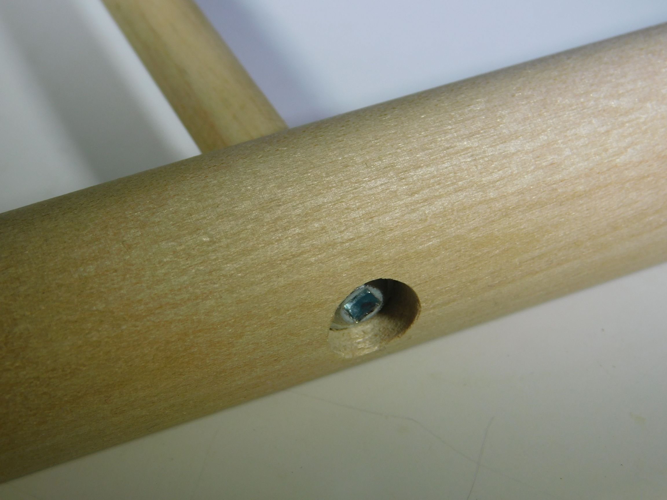
I came up with the clamping dowel idea used here when I made a cargo box for my electric motorcycle.  It clamps the cargo box to the cycle frame beam. This router table is a good application of that idea. 
Cam dowel clamps the router table tight to my bench
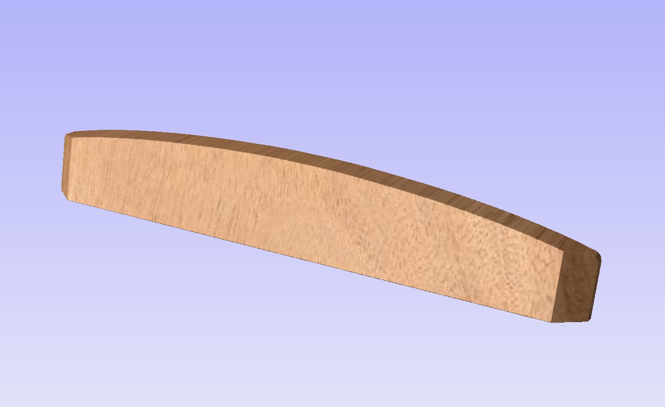
Ends of the 1" dowel have an offset 3/4" section. Pull the smaller dowel handle toward you and horizontal to release the cam and remove the router table from the bench edge. 
Render from my CNC Software

A dust shroud came with my Milwaukee trim router.  Having the router mounted in a table is a good opportunity to put that shroud in place, hook it up to my dust vac, and see how well dust/chips are collected as it runs. I oriented the router so the shroud opening is forward for easy connection to my dust collector hose.  

Dust Vac Connection

The 14" square top greatly extends the support surface. A fence can be clamped to it for straight guided edge cuts or cuts parallel to an edge using bits with no guide bearing. 

Quick release fence.
All plywood parts except the fence were cut from a 16" x 25" inch rectangle of Baltic Birch 12mm plywood. The dowel used is 1" diameter and 8.25" long.  Offset ends are 3/4" diameter.  I used my CNC to cut the ends, but this could be done on a lathe using offset centers. 

I know I'll get plenty of use from this clamp on trim router table.  Advantages of the design:

  • No floor space is needed. 
  • It is easy and quick to install and lock onto the bench edge.  Easy and quick to release and remove.
  • No other clamps are needed to hold it on the bench.
  • The fence is quick to lock down or release to reposition or remove. Flip over the cam levers  to lock or release it. 
  • It extends the uses for a trim router.
  • The battery powered Milwaukee trim router means no dealing with plugging it in to use.  

I stow it under my bench when I'm not using it.

Comments and Questions are welcomed and appreciated.  No ad links in your comments please.

4D 


Wednesday, April 16, 2025

A Simple CNC Rotary Axis Project. A Lathe Tool Handle.

Oak handle for a parting tool
This handle design is a close copy of one I made while in my first college furniture design class.  All students were given a tool with no handle, and challenged to design and make their own handles for them.  Mine was a parting tool.  This project is also for a parting tool.

Handle and Blade
All projects made from wood require some prep work, and this was no exception. First came finding some wood scraps long enough and wide enough.  Job done.  Next came gluing them together to get close to the final thickness I was after.  Job done. Scrape off any dried glue that oozed out, then joint one side square to the front and back faces.  Jobs done.  Next to my table saw to rip the block to just a bit wider than 1.5".   To mount it on my rotary axis I glued a 1.5" diameter circle of plywood to one end with some paper between the plywood and board end. The center was carefully marked on the other end.  Then a 1/8" hole, 1/8" deep was drilled in the center.  This for the tailstock to pierce.   

First step after mounting it on my radial axis was to turn the square block into a cylinder. That was done with a pocket toolpath at 0 depth, spanning across the surface. As the rotary axis spun this toolpath trimmed off the high corners, leaving a nice straight cylinder. 

The ferrule end was done with a pocket toolpath.  The contoured surface was done with a moulding toolpath and a ball nosed bit. 

Done with the initial slope.

Over the hump and almost done.

CNC is done.

Once the CNC was done with its work, I took the block out to my mini lathe to sand smooth and trim off the back end. 

Handle and the tool it will hold.
A 12mm hole was needed in the tip for the tool blade. Done on my drill press. 

I'll put some Danish oil or Tung oil on the handle to finish it, and I may v-carve my initials in the back end.   I'll update this post with final finished beauty photos when that is done.

The End.
4D
 

Wednesday, April 9, 2025

Small table and a white pipe.


In an effort to use up materials I've collected over the years, this project employed a section of white painted pipe as the structural post of a small table. The table top I made awhile back as a challenge to use up scraps of short lengths of wood.  Scraps ripped and tipped and glued together to make a roughly 10" x 10" panel, then CNC cut into an interesting shape and bottom contour. 

The top needed some structure to hold it horizontally above the floor.  18 to 24 inches tall was the desired height I wanted the table to be. I have at least 3 identical section of white pipe.  One pipe alone made for a simple design.  I just needed to come up with a structural way to connect it to the top and a base that spreads out the load so the table wouldn't easily tip over. 

Connecting wood to metal pipe was the challenge. I deformed the end of the pipe to a shape that wouldn't spin in a pocket.  I chose a hexagon for the end cross section.  I had to CNC cut a negative form to press the pipe into using my bench vise.  
Round to Hex over 2 inches

1" thick HDPE I have on hand, so I cut forms from it. High density was the desired quality.  I didn't want a form that the steel would deform before the form could reshape the steel.  
HDPE worked.  
With a way to reshape the pipe ends, making a pocket for the hex ends came next. To hold the pipe between table top and base I ran a length of 1/4-20 all-thread through the pipe. I used a cap nut on the top and a nylock nut on the bottom end.  The bottom nut will be under the base and not seen.  The top cap nut is decorative, flush, and in the center of the top. The pipe runs straight up from base to top.   


It took two tries to cut a pocket that the ends of the pipe would slide into.  I checked the fit while the board was still on my CNC.  Next step was to simply enlarged the vectors used, recalculated the toolpaths and cut again. I had a 1 degree taper on the sides of the hex hole, and although the pipe can be drawn in I fear the board may split.  I replaced the initial block making a new one with a simple pocket with straight sides. 

A simple base design came next.

The center wood block has a board on each side. The boards extend to be the feet of the table.  The boards half-lap/interlock to surround the center block. 
Base slat with slots
I designed a wedging half lap joint cut with a CNC, and used it in assembling the 4 base boards.  A spline in two sides of the block and two of the surrounding wood slats will structurally keep it in place. Glue will do the rest. 
 
Base slat edge refined
To refine the edges of the base boards I drew a curve that when intersecting each board would be 3 degrees from horizontal.  Knowing I had a 3 degree tapered router bit I then cut the curves using that bit. Look close at the base of the table in this photo and you'll see the crisscross pattern curves all blend together. 


Now that all parts are made and assembly is verified, It is time to put some stain and top finish on the base boards and the table top.

I'll add a photo here when I have the table stained and finished.

Comments and questions always welcomed,
4D

Sunday, April 6, 2025

Tapered Radial Finger Joint

Tapered fingers
Mating side


Advantages: 
- The two halves slip together easily. 
- They fit tight when fully together. 
- When assembled they have a unique look.
- Mating surface don't touch until fully together.  No scraping off glue when assembling.  

Renders above are from my CNC software. 

This joint was not easy to create the toolpaths for.  It took drafting skills I learned in high school and the great drawing tools in my CNC software to create.  Tips of the fingers are the same width as the valley between them. One half fills the center area left by the other half.    The tapered sides were accomplished with a 3 degree tapered end mill.  It has a 0.125" diameter tip, 3 degree tapered sides, and just a little over 1" of cutting depth. 

I'll use this joint for top and bottom zebra wood caps on 1.5" diameter cherry dowel legs. Applications are anywhere you want to join round wood parts end grain to end grain. Only limited by your ability to clamp parts vertically within your CNC cutting limits. If you do use this joint please consider referring those who see it back to this post.  

With straight cut finger joints there is always a conflict of fit. A battle of wit. Too tight and the fingers may not fit together at all. A perfect match and while they do fit together they are a challenge to assemble and any glue in the joint gets scraped away when you do assemble them.  Make the joint looser and you have a loose fit that glue ends up filling across gaps. By CNC cutting with 0.001" accuracy the fit of these tapered joints is both easy to apply glue to and assemble, and will go together tightly with even contact between inner surfaces.

3 degree taper between fingers. 
Test cut example. It is critical to center the toolpaths for each side of the joint. Check back for final project images. 

Comments are encouraged and welcomed.

4D   


Wednesday, March 26, 2025

CNC cut Hardwood Dowel Joinery

My first job out of college was for a furniture company noted for the metal framed residential furniture they made and sold. It was all designed to quick assemble.  No welding of metal parts. Clever engineering of steel connections made their furniture go together rigid and precise. One connection they used between small tubing into larger tubing was to taper the end of the small tube, then pull it tight into a slightly smaller die-punched hole.  This post is about a wood version of that connection.  

For this sample a three degree tapered end mill, a 3/8" diameter wood dowel, and a 1" diameter wood dowel are used. 

Taper the dowel and the hole

A 90 degree connection that wedges tight and stiff with no glue.  Draw tight with a wood screw. 


Pocket hole screw

Clean, precise, and easy to create.

The small dowel end was pre-drilled for the pocket hole screw. 

Pre-drilled for screw threads
Trapped tight in the tapered hole there is no chance the small dowel would split. The counterbored hole for the screw head could be covered with a wood plug. For a coffee table or end table a frame made from dowels using this joint could have the side frame pre-assemble and only require the end stretcher dowels to be screwed into the legs.  A simple wood frame that is rigid with clean joinery and no glue required. Hardwood dowels are available in many species. Imagine a tempered glass top resting on the frame to finish it off. 

Taper theory:   Wood dowels are imperfect. If they have been exposed to humidity changes after production then they are usually out-of-round by a few hundredths. Drill bits make round holes. A straight dowel end (likely a bit wider than thicker) into a straight hole drilled into wood is either loose in one axis, loose all around, or so tight you have to pound/press it into the hole. Pressing it into the hole will wear off the fat side or deform the hole to accommodate the oblong dowel end.  Use a CNC with precision down to 0.001" to recut the end to a "perfect" tapered shape and a "perfect" matching tapered hole. There is no abrasion between dowel and hole when inserting until near the bottom when the tapered sides start to press against each other. Tapping or pulling the dowel in the last 1/32" or so presses the sides together.  Uniform contact around the perimeter. Friction all around. 

Comments welcome!
4D


Monday, March 17, 2025

Whimsy in Design. Magnetic Appeal.

Whimsy
I started with a small table top made for a rejected project.  I added in a couple of 36" long 3/8" diameter dowel rods I've had for a couple decades or more. I cut them in half to be the legs.  Then I made 4 wood balls.  I mixed in some 3/8" diameter magnets left over from a previous project, and this is the result. 

I drilled holes for the dowel legs in the bottom of the table top using my CNC.  I wanted the dowels to angle out rather than stand straight up, so the CNC jig was tilted 5.8 degrees down from horizontal. 
On my Compound Angle Clamping Jig 
Rather than glue the dowels in, I embedded magnets into the bottom of the CNC drilled holes.  Since wood won't stick to a magnet, I inserted metal screws into the ends of the dowels. The biggest challenge was centering the screw heads on the dowel ends. A bit of filing might have happened to make them slip easily into the holes. 
Embedded Magnet
The holes in the top were limited in depth by the screws that held the magnets in place. Any deeper and the screws would have poked out the top.  An ideal design would have deeper holes to better brace the inserted dowels. 

For feet I made wood balls, 1.5" in diameter.  They need a 3/8" diameter hole in them.  They will get magnets in the bottom of the holes and as such also stick to the screws in the ends of the dowels.  For whimsy I'll painted one of them red.  Experience tells me the one red shoe will make the table more memorable.  

I gave my CNC rotary axis a chance to prove it could make wood balls.  
Five Maple Balls on my Rotary Axis

Five 3/8" Diameter Holes

One Ball, ready to trim. 
Four wood ball feet.  Ready for magnets and a finish.

Rare earth magnets hold all the parts of this table together.  You could replace the wood dowels with steel rods and skip having to add screw heads to the end of the dowels.  That would add considerable weight, sterilize the composition, and require paint to prevent the metal from rusting.  The wood dowels are just enough.  No more than needed to hold up the top. When whimsy strikes you can pop off the ball feet and replace them with perhaps a seasonal color alternative.  How about 3D printed shoes to slip over and magnetically stick to the dowel ends?
 
All projects survive longest if the parts have some finish on them.  I set about first applying clear finish to the wood balls.  No problem with the first three, but the 4th ball protested.  It tried to escape by rolling off the bench, but I caught it. It got so angry at the thought of joining the clear finish crowd that it turned red in the face.  In the end it got its way.  Meet the angry red shoe.  I may have to rename this post as "A Table with One Angry Red Shoe.  
One angry red foot.
The ball feet balance the composition.  An echo of the thick top. They recognize the thin dowels as official table legs. Although this little table stands up proudly, the thin dowel legs happily flex a bit, and a bump against the table top will reward you with a quick wobble dance. Not a table you'll want to sit on. Not a table for anything like a small TV.  Park the TV remote and maybe a coaster with a drink on the top. A frail little table such as this one needs a place out-of-the-way.  Where no one might accidently bump it.  Not in the open where predatory beasts in the house might find it. A more stout version with thicker and stiffer legs would eliminate the wobble, but also remove the joy the table elicits when it does dance a bit.  😉

Comments welcomed and appreciated.
4D