Search This Blog

Monday, March 13, 2023

A Tool Stand for my Taigtool CNC Mini Milling Machine

I've got a new benchtop tool on order and it needs a stand to rest on. There will be associated accessories for this tool so a drawer to keep them in will be useful. The top of the bench has been made and was made from a 25" x 48" x 1.5"thick butcherblock panel purchased from my local Menards.  See here how I made the rectangular panel into a square panel: Square from a Rectangle

To access the tool without having to bend over the bench will be 38" tall. The legs will be similar to those I made for the prototype bench you can see here: Hobby Bench

Made from 4x4 (3.5" x 3.5") Cedar legs and 12mm x 5.75" plywood stretchers the flared stance should be sturdy and steady when the machine is in motion. 
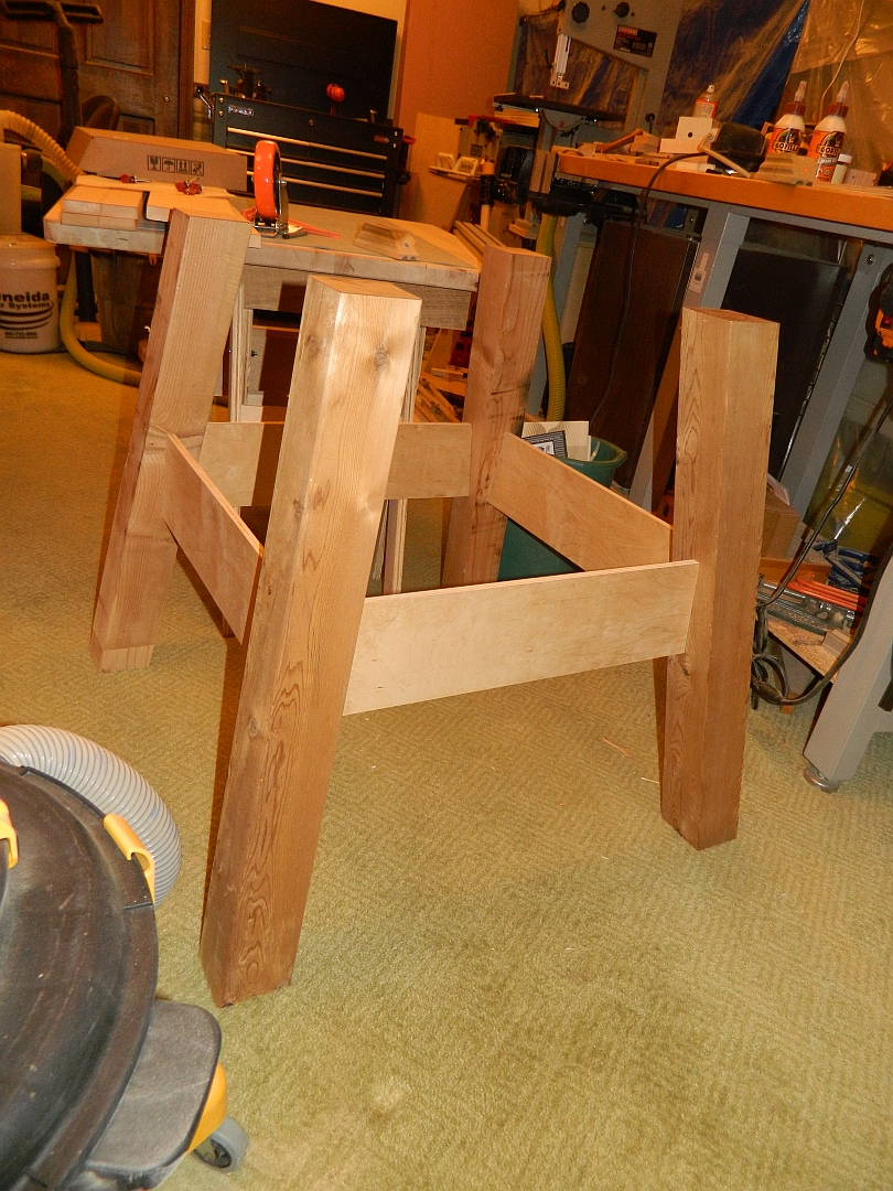
8 degree legs

The drawer will use 24" long soft closing full extension drawer slides. The stand may eventually have casters.  

I found 6' long 4x4 cedar posts at my local Menards store. Fortunately six feet of material is the longest I can fit in my small car.  Six feet of 4x4 is enough for 2 legs.  I made all 4 legs with very little waste from two 6' long posts.  My Bosch Glide compound miter saw was used to cut the top and bottom compound angle on all 4 legs. 

The tenons on the end of the 12mm thick plywood stretchers were cut on my CNC.  They were clamped vertically in the X plane and held at 8 degrees relative to the Y direction. 

Mortises on two sides of each leg were also cut with the legs on my CNC. They are at an angle to end up vertical in relationship to the angled legs. 

Mortises at 8 degrees

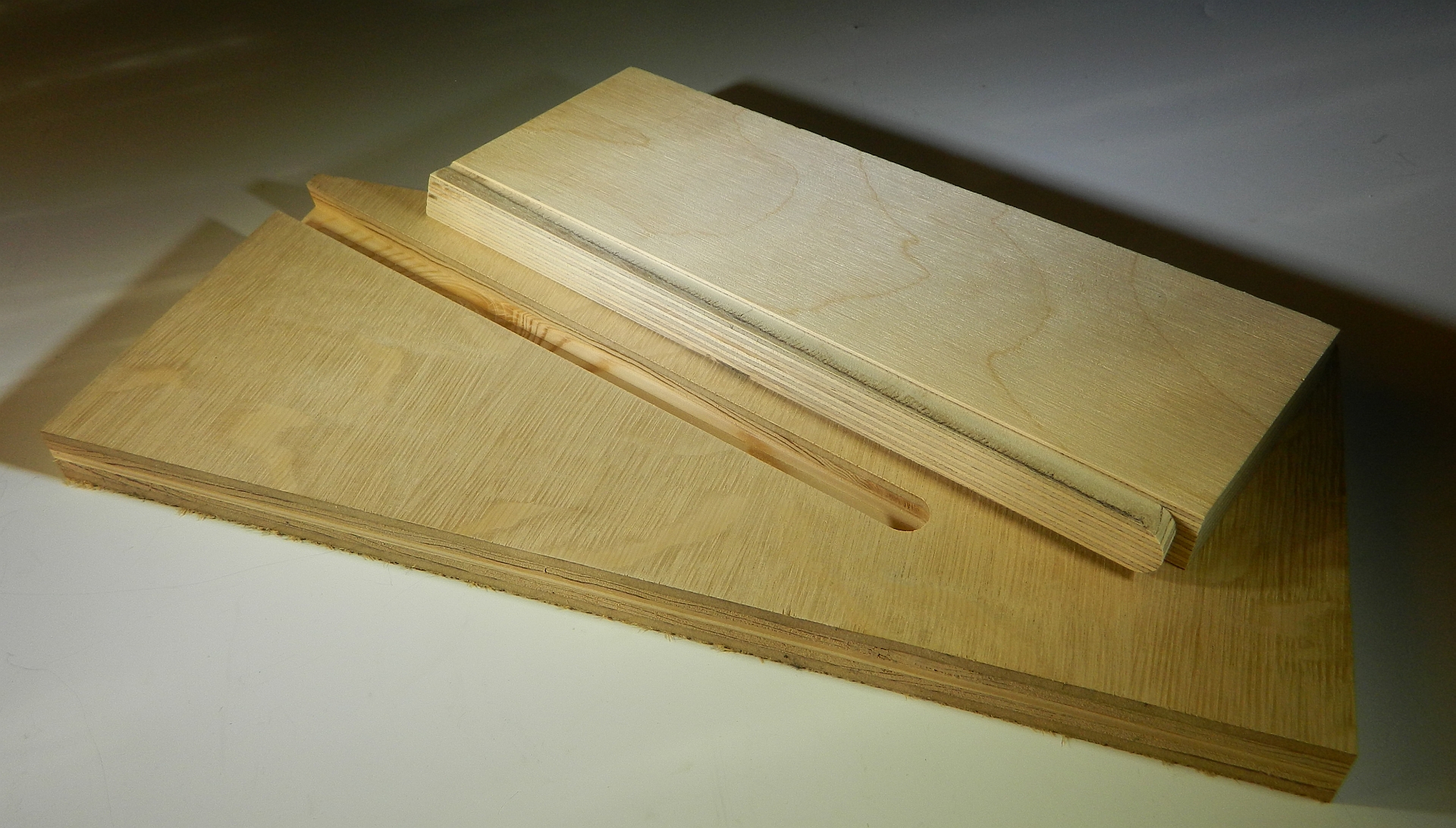
To make the drawer side rails I split a pine board in half and ran both halves though the drum sander until the bandsaw marks were gone. I cut the two pieces in half lengthwise, then glued each half side by side to make two wider boards I can use. A new resaw blade on my bandsaw took awhile to install and set up, but did a nice job of splitting the pine board in half. 

For the two drawer sides I found two 6' long pine 1x3s that would do. I cut them in half lengthwise, then joined one edge on each piece before gluing 2 together x 2 stretchers.  With the glue dry I scraped off any beads of glue, then took all 3 stretcher boards out to my drum sander to clean them all up. They ended up 3/4" thick. 

Next came finalizing the design drawings and verifying the dimensions that all the parts needed to be. 

Drawer rails were made, including the tenons on the back angled end.  Mortises for those tenons were cut on the top inside edge of the two rear legs.  A pocket for the rails has been cut on the side of the two front legs. 

Legs will have their outer corner rounded over by a 1" radius round over bit.  The outer two faces of each legs have been cleaned up and made square to each other on my small jointer. 

Fence for 1" Radius Roundover Cutter
I designed and made a fence for my router table that would work with my 1" radius roundover bit.  I then took all four legs of the base out to my garage shop and ran their outside corner through that 1" radius roundover cutter. The outside corner 1" radius is to match the 1" radius corners of my table top. Some detail continuity to ensure the base leaves no question that it belongs to the table top. After that all legs were sanded to clean up their sides, and a 1/4" radius roundover was cut on the two inner external corners.  

For the drawer I've decided to use finger joints on the corners.   I've already CNC cut the profile for the drawer slides on the two sides of the drawer.  I cut the finger joints on the 4 corners of the drawer box. I used a 12mm router bit to simplify making a slot in the box sides for the 12mm plywood bottom. While I could make a 12mm wide slot with two passes of a 1/4" bit, it simplified the job by having a 12mm bit for that task.  Most 1/2" plywood sold these days is actually 12mm thick.  

 Drawer assembly started with one end (two corners) being glued up.  

24 inch deep drawer.
After the glue was dry on the first end, the other two corners were glued up.   This drawer will slide between two rails that were glued to the base.
These rails will hold the drawer slides for the drawer. 

The articulating "feet" for my parallel clamps helped clamp these parts efficiently. 

Finger joints on the drawer box needed to be flush trimmed to the side contour.  A 1/4" spiral flush trim bit in my hand held Milwaukee router took care of that.  
Finger jointed corners
With the drawer all glued up and finger corners cut flush the drawer was ready to have the drawer slides mounted and fit into the stand. 
Assembled drawer
I applied iron-on birch veneer edge tape to the plywood stretcher edges. When all the parts were done, and rough assembly was complete to verify fit, I took the bench into my utility room to help verify space and association to the PC work station. I might swap these two so the CNC mill will be centered on a wall rather than in a corner. 
I addition to this milling machine I plan to add a metal cutting bandsaw and a metal cutting miter saw to this room.  The bandsaw already has a base.  The miter saw will need a bench to sit on.  I ordered a ready made portable worksite stand for it from Amazon. 

The CNC mini milling machine will arrive soon.  The table top has been handy as I've been working on clearing out more space in this room for other metal processing tools. I need to clear off the table and apply 3 or more coats of finish on it to protect it. 

Assembled the base was a little racked, and the drawer didn't close evenly.  My hopefully temporary fix was a belt clamp between opposite corner legs. 

This table as intended is very stout and firm. When the CNC milling machine arrives I expect it to be happy mounted on this bench. 

Questions and Comments are encouraged and welcome.
4D
 

Sunday, January 29, 2023

Making a Square Table Top From a Rectangular Butcherblock Countertop.

I enjoy using wood for my projects.  If the shape or thickness of a board is not what I need then I can usually reconfigure the wood to make it into what I need for a project. 

This post is about dividing a 25" x 48" x 1.5" butcherblock panel so that the parts can be reassembled into the largest possible square. A little iterative drafting and some easy math is all that is needed.

Math comes in handy to calculate how much area the butcherblock panel has, and with allowance for the kerf cuts to divide it what will be the largest square that can be made with that same area.

Multiply 25 x 48 to get  1200sq.in.. If no material was lost when dividing the butcherblock then the largest possible square would have sides that are the square root of 1200 or 34.61". 

My CNC software has a handy tool for measuring the area within any outline. I'll use a 1/4" diameter router bit to cut the butcherblock into 3 pieces.  The length of those cuts times 0.25" will be the area lost from kerf cuts. Subtract the kerf cut areas from 1200 to find the final maximum size of the square that can be made. 

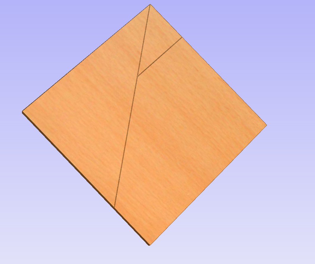
These are the two lines I cut to divide the rectangular butcherblock panel. 

Subdivided panel.
After being cut the parts are put back together to make a 34.45" x 34.45" square. 

Reassembled Square
This table top will be mounted to a cedar legged base I made. 3.5" x 3.5" legs with plywood stretchers. I'll attach the base to the top with crazy 8 connectors. 

Of course reality comes into play when actually making the parts.   This butcherblock panel claimed it was 25" x 48", but it was 1/8" narrower.  It also came with edges that had been rounded over.  When the small triangle piece moves to its position in the square its bottom rounded edge meets the top rounded edge of the large piece, Trimming those edges to get past the round over shifts the small triangle in, losing about 3/8" of length as it tucks into the corner.   The final "square" will now be 3/8" smaller in one dimension. 

To start I could have ripped off 1/8" of both the left and right side of the initial board, and recalculated the  geometry to make a slightly smaller square from a narrower starting board.  This butcher block panel is roughly 80lbs of wood.  It was a challenge to lift up and place on my CNC.  In place it doesn't slide without a significant effort.  To run it twice through my table saw would have been far more work.  

To clamp the 3 boards together as a square I used 4 long parallel bar clamps. Two laid down in one direction and the other two over those to keep the triangles aligned and in place. 

Reconfiguring rectangles of most lengths and widths is possible.  You start by making sure your starting and ending areas are the same. Subtract the area for kerf cuts you have to make, and verify that the board you start with is actually the dimensions you used for your calculations. In "Mathematical Puzzles & Diversions" by Martin Gardner (←Amazon link) it shows how to cut an equilateral triangle into 4 pieces that can rotate around to make a  square. Some day, maybe, I'll make a triangle from this now-square table top. ;) 

Questions are encouraged!
4D
  

Thursday, January 12, 2023

Adventure Cutting Aluminum with my CNC

This is my tale of trying to cut some 6061 aluminum to make an aluminum version of a push button depth stop for my Wen benchtop drill press. 

I bought a 4" x 6" x 3/4" thick piece of 6061 aluminum from Amazon. From this I cut the body of the depth stop.  I also have a 5/8" diameter rod of aluminum I used to make the button for the depth stop from.  

Some web research found recommendations for feed speed (17-24rpm), plunge speed (6"/minute), depth/pass (0.03") and bit RPM (13,000) to use when cutting aluminum.  My CNC uses a variable speed Dewalt router that can be set at the recommended speed. The other variables I can set for each toolpath in the CNC software I use (Aspire from Vectric.com). 

My first try was to cut the perimeter and center hole of the press button body from the 4" x 6" block.  I set up the job to cut the part near one corner of the block. The bit I used was a 3/16" spiral upcut end mill.  Two sides of the cut were 1/2 the bit width from the edge. The other 2 sides were full width cuts through the aluminum block.  I thought all was going fine until about halfway through the aluminum. At that point I started hearing more chatter from the bit as it made the full width cuts through the block.  With 1/8" or so to go the chatter was so bad that I had to stop the cut.  I took the block off the CNC, then cut the part free from the block using my band saw.  I then used a spiral flush trim bit on my router table to trim off the remaining aluminum from the bottom edge. I held the part with a c-clamp as I fed it through the flush trim bit.  The bit speed was also turned down to about 13,000rpm. 

First attempt
With the part free from the CNC I could see the affect of the bit chatter on the revealed side. Measuring it with a digital caliper it was close to 1/32" too small in both X and Y direction. the center hole was also not centered between the sides as it should have been.  The deflection from the full width passes was clear.  

With a night to contemplate what had happened I decided to try again the next day. It had been full width passes and ramping down that my CNC had trouble with. The conventional profile cuts had deflected toward the part.  

For my second attempt I started with a block only 1/8" larger than the final part. I rough cut out the body block from a machined corner of the original block using my bandsaw.  

No perimeter passes would be full width.  To avoid having to ramp into pocket cuts for the center hole I pre-drilled a 1/4"d hole (using my drill press) through where the pocket was to be cut. 

Holding the block in place for the cuts started with a t-track bolt up through that 1/4" hole.  A lock washer under a nylock hex nut held the block down tight to my spoil board. To make sure the CNC cuts didn't spin the block while cutting it I separated the cuts into unique toolpaths for each side. While any side was being cut I clamped a block against the opposite side. All profile toolpaths were climb cuts, and only through 1/16" off each side. Twenty two steps were used to get through the 3/4" thick block. All cuts were climb cuts so that any deflection would be away from the part rather than toward the part. 

Once the perimeter was cut I took it off the CNC.  Now I could clamp the part in my low profile vise to cut the center hole. Starting each pass in the center 1/4" hole I had no need to ramp down between passes.   When done I again measured the part and found it to be within .01" of the intended size. The hole was perfectly centered as it was supposed to be. 

Part with hole in top and side. 
Next came cutting the elliptical hole in the side for the button.  I again used a smaller drill bit to drill an opening in the center. With the part clamped side up in my low profile vise I used profile cuts on-the-line to start in the opening before cutting around the perimeter of the elliptical hole. 22 passes again for roughly .75" of depth.  The elliptical hole measured exactly the intended 1/2" x 5/8". In the bottom of the elliptical hole a smaller round pocket was cut for the conical spring. 
Conical Springs.
With all the holes in the depth stop body complete, my attention turned to making the elliptical button.  The button was cut from a 5/8" diameter aluminum dowel.  With the dowel clamped vertically I did a 3D cut to round off the top end of the button.  Then I milled a flat surface down one side of the dowel.  Clamped flat on my CNC with the flat side up I used a 90 degree V-bit to mark exactly where the first 10.8mm hole would be pocketed. 

On my drill press I drilled a 1/4" diameter hole through the dowel.  This center hole would provide room for a 3/16" bit to drop down for each pass before cutting the perimeter of the hole. No ramping needed. 

I used my M12 tap to thread the 10.8mm, hole.  

Next to and overlapping this threaded hole I cut a 12mm hole so the button could slide over the depth stop post.  Each pass started in the open area before moving out to cut the perimeter of the hole.  No ramping needed. 

Holes done, and all that was left was to cut the elliptical shape from the 5/8" round dowel. 
My first try reminded me that a spinning bit in a router will exploit any weakness in how a part is clamped.  I had clamped the aluminum dowel vertically against my vertical clamping jig and a vertical reference fence.  Quick grip clamps held the dowel in place.  This is how I normally clamp down wood dowels.  

Within a few seconds of contact to the dowel the part shook. A clamp fell off, and the part was twisted away from the bit before I could hit the emergency stop. Clearly my clamping strategy had not been good enough. 

I tried again, only now moving my low profile vise to the vertical jig so I could better clamp the aluminum rod in place. 

With the dowel now held securely I tried the same toolpath again.  This time I slowed it down 50%.  A few minutes later I had an elliptical button on the end of an aluminum dowel.

I cut the button free from the dowel at my bandsaw. I then clamped it into my bench vise to file the rough end down smooth.  
Depth Stop Collar Assembled
Almost surprised that the button slipped cleanly into the elliptical hole of the collar.  This depth stop collar works great on my drill press. The strong conical spring keeps the internal threads pressed hard against the threaded post.  Pressing the button in lets the collar move easily up or down the post. 

Low profile vise:  Plywood Vise You Can Make!

HDPE version of this depth stop: Making a Push Button Depth Stop

Comments and questions are encouraged!
4D

Sunday, January 1, 2023

Making a Push Button Depth Stop for my Wen Drill Press

I've made push button releases for a few past projects. In every case they made adjusting or attaching/releasing much easier to do.  This post is about how I make one to serve as a quick setting depth stop for my benchtop Wen drill press.  This is an initial prototype. Part of what it is for is to show me if it works well.  Any flaws that show up will be noted and fixed in the following prototype.  Test, update, and test again.  

Depth Stop
My Wen benchtop drill press currently uses a knurled nut you have to spin up or down on a M12 threaded post to set a stop. Tedious. For the push button upgrade I'll need an M12 fine tap.  I ordered this one from Amazon.com:
M12 fine tap

The depth stop works by pushing a threaded section against the threaded post. Push the button in and the threads are pushed back so the post can slip through the depth stop body. Release the button and the spring pushes the thread back against the post to stop it from sliding up or down. 

To make the push button return when released I'll need a small conical compression spring. I found this one that should work at McMaster-Carr.com:

Conical Springs

A 12mm drill bit is needed to make a hole so the button can slide easily up and down the 12mm post. I ordered this one from Amazon.com: 

12mm drill bit

To drill the start hole for the tapped threads I'll need a 10.8mm drill bit. I couldn't find a 10.8mm bit, but 27/64" is very close to 10.8mm.  I already have a 27/64" bit so I'll use it instead. 

27/64ths
For the prototype depth stop parts I'll use some HDPE. I have some on hand. I've chosen HDPE for this project because it is easy to machine, and somewhat self-lubricating. 

I started with a 1" thick scrap of HDPE. Milled an area down to .75", then cut the 12mm shaft hole and outer shape. 
Depth Stop Body

I removed the bar from the CNC to tap the hole. I trimmed off the bridges using a flush trim bit in a hand held router clamped in my bench vise.

The front edge of the depth stop now needs a 5/8" wide elliptical hole, 0.7937" deep for the button.

HDPE Body
In the bottom of the 5/8" hole another smaller hole .0.42"d and 0.1288" deep is needed to center the conical hinge. For precision I clamped the depth stop body vertically to pocket those holes using my CNC. 

The button itself is the key part to make this work. I cut the elliptical button from a 1" thick HDPE block. The steps to make it included:

1.  Start by drilling the 27/64" (10.8mm) hole through the side.  My low profile vise held the HDPE blank while this hole was cut.

2. Tap the 27/64" hole with the M12-1.25tpi fine tap. 

3. Next to, and overlapping 1/2 of the tapped hole drill or pocket out a 12mm hole though the blank. There is 0.121" between the centers of the tapped hole and the 12mm hole. 

4. Flip the block up 90 degrees, then use the CNC to shape the outer end of the button and cut the ellipse perimeter from the blank. 

5. Cut the button to final length to release it from the block.  I used my compound sliding miter saw to cut it. 

I made the button and hole it slides into an elliptical shape rather than a simple cylinder. This keeps it aligned with the post. The long axis of the ellipse is horizontal. There is no width to sacrifice given the 12mm hole is cut through it. 

Once assembled this prototype works as expected. It keeps the depth stop from moving up or down when the button is not pressed in. When the button is pressed in the stop can be easily moved up or down the post. 

On my Wen drill press
The one flaw is due to the post having a flat face rather than being threaded all around.  If the post was completely threaded then the depth stop could be fine adjusted by spinning it around the post. With a flat front the threads inside the depth stop disengage when spun to the front. Keeping the depth stop button at the front provides approximately 0.05" per step adjustment. Slightly less than 1/16" (0.0625")

For Aesthetic reasons only I'll likely put a small chamfer around the top and bottom edges of this depth stop. For the next prototype I'll see if I can make one from aluminum. 

For a more useful stop a shaft with 16 threads per inch would allow 1/16" per step adjustment.  A half turn of the button would move it 1/32".  A quarter turn would allow 1/64" step precision. 

Comments and question always encouraged and appreciated.  

4D

Tuesday, November 29, 2022

Making Bolt Hole Chamfers with an End Mill on your CNC.

I spent the last 10 years using CNCs without a tool changer. Whenever the job required a bit change normally I thought about how I might be able to do the job using just one bit and some creative use of the CNC software I was using. This is one example.

Projects that needed perimeter or internal chamfers were done most efficiently with a bit change to a V bit.  I have a project that is put together with flat head bolts. The need to chamfer the bolt holes could have been done using a drill press after the CNC was done. Figuring out how to chamfer a hole with the same end mill I used for all the other cuts turned a 2 process job into one CNC  job with no bit changes. 

Vectric.com's Aspire and VCarve programs have a fluting toolpath.  Fluting takes a vector and ramps the bit down or down then up with the bit being centered on the vector. A circular array of 9 (or more) short vectors centered over the bolt hole, using a bit no larger than the diameter of the hole, can effectively chamfer the perimeter of the hole from the bolt head diameter down to the hole edge.  Using a small bit (1/8" or 1/16") may require a greater number of vectors to result in a relatively smooth chamfered edge. The chamfers in this image were made with a 1/4" diameter end mill. 

2 x 2 Hole Array
The slope of the chamfer and the diameter can be easily changed.  Aspire/VCarve also have a circular array layout tool that will use one vector that spans the hole and make any number you specify of rotated copies around the same center. Using an odd number of vectors results in a circle of lines with alternating start points.  Alternating the start points reduces the travel time needed move to each successive vector.  
Vectors Used
The center of the bit used is what follows the line. The depth the bit will slope down is set when creating the fluting toolpath.  In the image above the shaded area is a shadow of the area the 1/4" straight bit travelled over.  The short vectors used are shown in red. The center circle was the hole for the 1/4" bolt shaft. Depth of the fluting chamfer cuts was 1/8".

I made the vectors for one bolt hole, then simply copied them to all the other bolt locations. 

You can find downloadable  .CRV3d and .CRV file of the sample above on Vectric's user forum: Vectric.com

Questions or comments are encouraged!

4D


Sunday, November 27, 2022

A Domino Slot Template.

Using Festool's Domino floating tenons is usually an expensive upgrade for hobby woodworkers.  The machine to cut the slots can cost over $1000, and the tenons themselves are more costly than traditional dowels made for joining wood parts. 

There are other less expensive sources for the floating tenons.  Attempts have been made to build simpler machines that duplicate the slot cutting action of the Domino machine.

I design and build furniture, and have found that floating tenons come in handy for connecting parts.  I can't justify the cost of a Domino machine, but I do have a small CNC and with it I can make the slots for ready made tenons on most furniture parts.  For joining long boards together I've designed a simple template that can be used with a handheld plunge router using a template bushing. 

A Domino Slot Template
This template could be made using a router table.  I drew up the template for cutting out with my small CNC.  The slots in the sides are for screws that would hold wood guide strips.  The guide strips can be adjusted to center or offset the slot that will be cut by the template. The template can be clamped to the edge of your board to stay in place when being used.  

A 5/8" diameter bushing in a plunge router base used with a 3/16"d spiral upcut router bit is all that is needed to make perfect sized slots for commercial Domino brand tenons or alternatives.  Some plunge bases for routers come with a dust collector shroud to suck away the chips as the slot is being cut. 


Plunge Router with Template Bushing
  This template is for 6mm x 20mm tenons. 40mm length. 
Slot has been Cut
You could make templates for each available size of tenon. All that needs changing is the size of the center hole. With floating tenons available in large quantity packs each size template would get plenty of use. The guide strips could be removed and used on whatever template plate is needed. A stack of different template plates would cost far less than the cheapest Domino machine you can find out there. 
A Good Fit
Once the template has been set up for the material, making several slots along the edge is relatively easy.  It just requires undoing the clamps, sliding the template to new position, then clamping it in place. Modifying the template for thicker or thinner material takes no longer to do than adjusting the fence of a Domino machine for the same job.

It is also easy to change the slot hole so you can use 5mm or 6mm bits to make the tenon slots.
For metric bits

If you use Vectric.com's VCarve or Aspire a files for these templates can be found on their forum HERE. 

Comments and Questions are encouraged!
4D


Wednesday, November 16, 2022

Tapering French (Sliding) Dovetail Joints for Ease of Assembly

Tapered French Dovetail 
French dovetail joints are a good way to connect critical cabinet parts.  A straight dovetail slot is easy to cut with a straight edge, router and a dovetail bit.  The mating male end of the joint takes a little more care to size right.  I've used a router table with the same dovetail bit and a tall fence to trim off the sides of the mating part end until the dovetail end fits snuggly into the slot. 

On wide boards a snug French dovetail joint can be difficult to slide in place. Friction builds up the farther into the slot you go. Getting the joint closed occasionally requires the pull of a bar clamp or tap of a wood mallet. The tendency of wood panels to bow or flex a little can add to the difficulty.  

Tapering the routed slot is fairly easy.  Make a straight slot against a straight edge first. Then move the leading end of the straight edge over 1/16" or so. Make note of how far you moved it.  A penny (1 cent) measures almost 1/16" thick (.06" rather than .0625"). I usually moved the straight edge end 1/16". 

To taper the male dovetail end a shim as thick as the amount the straight edge was moved is needed.  I tape a penny (tape + penny=1/16") or laminate sample chip to one edge of the mating piece just above the height of the dovetail bit. As the board slides past the router bit that shim holds one end away from the bit 1/16" to effectively taper that cut. The other side is cut parallel to the face. Care needs to be taken to match the side of the tapered slot to the tapered side of the joining piece. Cut on the wrong side the joint will still slide together, but be slightly crooked when in place.

CNC cut Dovetailed Side

CNC cut Tapered Slot
Using the CNC to cut the tapered slot is easy. The CNC cut tapered slot can be centered so there is no chance of ending up with a crooked panel. A vector that starts at the beginning of the slot, runs to the end of the slot, then returns to the beginning 1/16" away from the start point is all that is needed.  A profile toolpath centered on the line with cutting depth set for one pass for the dovetail bit will cut the tapered dovetail slot. 

Vector for Tapered Dovetail Slot (blue)
In the drawing above the green circles represent the diameter of the dovetail bit at beginning, middle, and end of the vector. The red lines show the width of the intersecting board. Blue is the vector needed and it is extended outside of the board by half the diameter of the bit.  This lets the bit drop down to cutting depth before it enters the edge of the board. To ease the stress on the dovetail bit I usually run a 1/4" down-cut spiral end mill on the same vector to clear out the slot before the dovetail bit runs to undercut it.
Vector for Male Dovetail End
Cutting the mating end requires being able to clamp the mating board vertically and level under the CNC spindle.   Making the toolpath to move the dovetail bit around the mating end requires some careful drafting.  You need to know the side angle, diameters of the dovetail bit, and depth of the dovetail cut.  Offsetting the male toolpath vector from the vector used to make the tapered slot will ensure a matching taper.  The amount you offset that vector is the necessary detail to come up with.  See the diagram above. One half of the bit tip diameter plus 1/2 the bit diameter at the cutting depth is how far you should offset the vector. I use a section view of the dovetail bit to find the cut depth diameter of the bit.  
Almost together. Still loose.
Alternately you could simplify the CNC toolpaths to duplicate the result of doing it without a CNC.  This is easiest if the dovetail isn't blind, and runs completely though the board. Two vector lines, with one slightly angled, to run the dovetail bit down on-the-line. To make the mating dovetail you'll need one pass down one side of the board, and an angled pass down the other side of he board. Placing the vectors for these requires knowing the bit tip diameter and the diameter at the cutting depth on the bit.  

With all CNC cut joinery the precision fit can be hard to nail down.  Using the same vectors and precise offset leaves no room for error or glue. I prefer to do the male side of the joint first, then the female slot.  I leave the slot side on the CNC to check the fit before unclamping it.  If the joint doesn't close completely you can reset your X axis (or Y axis depending on how you clamped up the board)  by a few thousandths and run the dovetail bit toolpath again.  I find .003" is a good amount of offset between sides of the joint for a good snug fit with room for glue. With sliding French dovetails it should take just a tap or two of a wood or plastic mallet to close the joint completely.  I tweaked my sample until my joint took two taps to close and will take the same two taps to free it up. 
Snug and Tight when completely together.

Comments and questions I encourage and welcome. 

4D