|
| Tapered French Dovetail |
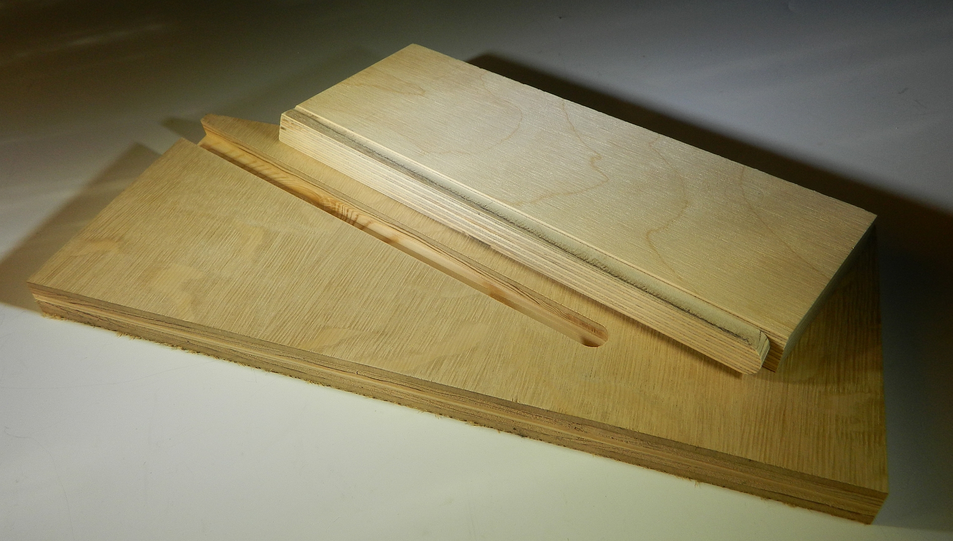
French dovetail joints are a good way to connect critical cabinet parts. A straight dovetail slot is easy to cut with a straight edge, router and a dovetail bit. The mating male end of the joint takes a little more care to size right. I've used a router table with the same dovetail bit and a tall fence to trim off the sides of the mating part end until the dovetail end fits snuggly into the slot. On wide boards a snug French dovetail joint can be difficult to slide in place. Friction builds up the farther into the slot you go. Getting the joint closed occasionally requires the pull of a bar clamp or tap of a wood mallet. The tendency of wood panels to bow or flex a little can add to the difficulty. Tapering the routed slot is fairly easy. Make a straight slot against a straight edge first. Then move the leading end of the straight edge over 1/16" or so. Make note of how far you moved it. A penny (1 cent) measures almost 1/16" thick (.06" rather than .0625"). I usually moved the straight edge end 1/16".
To taper the male dovetail end a shim as thick as the amount the straight edge was moved is needed. I tape a penny (tape + penny=1/16") or laminate sample chip to one edge of the mating piece just above the height of the dovetail bit. As the board slides past the router bit that shim holds one end away from the bit 1/16" to effectively taper that cut. The other side is cut parallel to the face. Care needs to be taken to match the side of the tapered slot to the tapered side of the joining piece. Cut on the wrong side the joint will still slide together, but be slightly crooked when in place.
 |
| CNC cut Dovetailed Side |
 |
| CNC cut Tapered Slot |
Using the CNC to cut the tapered slot is easy. The CNC cut tapered slot can be centered so there is no chance of ending up with a crooked panel. A vector that starts at the beginning of the slot, runs to the end of the slot, then returns to the beginning 1/16" away from the start point is all that is needed. A profile toolpath centered on the line with cutting depth set for one pass for the dovetail bit will cut the tapered dovetail slot.  |
| Vector for Tapered Dovetail Slot (blue) |
In the drawing above the green circles represent the diameter of the dovetail bit at beginning, middle, and end of the vector. The red lines show the width of the intersecting board. Blue is the vector needed and it is extended outside of the board by half the diameter of the bit. This lets the bit drop down to cutting depth before it enters the edge of the board. To ease the stress on the dovetail bit I usually run a 1/4" down-cut spiral end mill on the same vector to clear out the slot before the dovetail bit runs to undercut it. |
| Vector for Male Dovetail End |
Cutting the mating end requires being able to clamp the mating board vertically and level under the CNC spindle. Making the toolpath to move the dovetail bit around the mating end requires some careful drafting. You need to know the side angle, diameters of the dovetail bit, and depth of the dovetail cut. Offsetting the male toolpath vector from the vector used to make the tapered slot will ensure a matching taper. The amount you offset that vector is the necessary detail to come up with. See the diagram above. One half of the bit tip diameter plus 1/2 the bit diameter at the cutting depth is how far you should offset the vector. I use a section view of the dovetail bit to find the cut depth diameter of the bit.  |
| Almost together. Still loose. |
Alternately you could simplify the CNC toolpaths to duplicate the result of doing it without a CNC. This is easiest if the dovetail isn't blind, and runs completely though the board. Two vector lines, with one slightly angled, to run the dovetail bit down on-the-line. To make the mating dovetail you'll need one pass down one side of the board, and an angled pass down the other side of he board. Placing the vectors for these requires knowing the bit tip diameter and the diameter at the cutting depth on the bit.
With all CNC cut joinery the precision fit can be hard to nail down. Using the same vectors and precise offset leaves no room for error or glue. I prefer to do the male side of the joint first, then the female slot. I leave the slot side on the CNC to check the fit before unclamping it. If the joint doesn't close completely you can reset your X axis (or Y axis depending on how you clamped up the board) by a few thousandths and run the dovetail bit toolpath again. I find .003" is a good amount of offset between sides of the joint for a good snug fit with room for glue. With sliding French dovetails it should take just a tap or two of a wood or plastic mallet to close the joint completely. I tweaked my sample until my joint took two taps to close and will take the same two taps to free it up.  |
| Snug and Tight when completely together. |
Comments and questions I encourage and welcome.
4D