Search This Blog

Thursday, September 8, 2022

Rocking Chairs: Fundamental Design Considerations

When I taught furniture design to college students I was often asked how rocking chairs work, and how to determine the rocker design and radius. Over the years my students designed and built several successful rocking chairs.

Here are the basics:

The center of gravity (of the occupant + the chair) will be directly over where the rocker arc touches the floor when at rest. The distance from the floor to this center of gravity has to be shorter than the radius of the rocker arc. The closer these two values are together the farther the rocker will roll. The farther it rocks the longer the rocking period will be. Ideally you want to use a rocker radius that creates a rocking period equal to the occupant's at-rest breathing rate. You don't want the seat plane of the chair rocking forward past horizontal. 

Let M = distance from the floor straight up to the center of (the occupant's) mass above the floor plane (in inches).  On a more upright rocking chair design, the M may be 23" to 25". R = Radius (in inches) of the rocker arc.  39" is a good R value to start with.
Rocking 5 degrees forward and back

When M is less than R, or your center of mass is lower than the center of the rocker arc, the chair will return to center when rocked forward or back because the C.O.G. has been lifted up and gravity will pull it back down. In the diagram above the C.O.G lifts .0575" with 5 degrees of rocking forward or backwards.  

The center position is when M is directly below the center point of the rocker arc. From a side view, M is normally located near the occupant's belly button when he/she is in a sitting position. For women it may be slightly forward of the belly button. A value for M can be found by positioning the user above the floor in a comfortable at-rest sitting position. Measure from their belly button to the floor to find M.
Centered Position

R > M, and a good dimension for R is 39" or so. Increasing R (flattening the arc) reduces the period of a rocking cycle. Reducing R increases the period of a rocking cycle. By changing R slightly the rocking period can be "tuned" to match the breathing rate of the occupant. The simple act of breathing will shift the occupant's mass, causing the chair to rock back with each inhale and forward on exhale.

Having your feet flat on the floor will impede rocking motion. Ideally the occupant's feet should cycle from touching toes to touching down the heel as the chair rocks. This suggests the height of the front edge of the seat should be 16" to 18" or so. Less if the intended occupant is of small stature.  

This all works because shifting weight moves the occupant forward or back from being centered. Since the center of gravity is straight down from the center of the rocker arc, moving forward or back lifts the occupant uphill. The incline gets steeper the farther one rolls.  Shift your position on the rocker and you will "roll" to another centered position. Relax back to your rest position and the rocker slows to a stop.

If your rocking chair tried to throw you out when you rocked forward then the center of the rocker arc is too far backwards. If your rocking chair feels like you'll fall over backwards when you rock back then the center of the rocker arc is too far forward. I've seen and sat in student rocking chair designs that suffered from one or the other mistakes. 

Rocking chairs are one design challenge that is worth making an inexpensive CNC cut prototype for.  

Comments and questions are encouraged and welcome!
4D


Tuesday, September 6, 2022

Iterative Progression

In furniture or product design often what you hope will be a good design ends up with obvious room for improvement. This is why initial builds are considered to be prototypes. It takes seeing and testing the first prototype to realize where flaws exist or where there is room for improvement in aesthetics or strength or performance or functionality or simplicity of build.

Shown here is a sequence of Balans style chairs I designed and made. Inspired initially by the original rocking Balans chair my pursuit was to find a design that was simple to build, adjustable, and stable.  In my PhDesk article photos you can see most of an earlier 3 caster perch version done as a class project by my students. The design was static with no adjustability or flexibility. Link:  PhDesk Article

Imbuia Wood Collapsible 
My Imbuia and leather prototype above improves on that earlier student design with knee pads that could rotate to meet your shins at a whatever was the most comfortable angle.   Initially the frame post beneath the seat was intended to be moved to different positions along the lower rails. This prototype revealed that changing the angle of the seat would also tilt the caster stems off vertical and reduce the ease of rolling the chair around. The frame could collapse by lifting the center post off the pin it rests on. Collapsed it would  fit in a smaller box for shipping or storage.
3 wheels Adjustable Height

Highest Perch Position
The 3 wheeled version above could be adjusted in height/angle.  This design isolates the caster base from the adjustability of the seat and knee rest. An aluminum push button  releases the aluminum post when pushed in and locks the post position when released. Knee pads pivot to meet shins at the most comfortable angle.
4 Wheels Adjustable

In use.
While there is an economic benefit to using 3 casters rather that four, a 3 point footprint comes with a flaw discovered in use. They could tip and roll out from under the occupant when leaning to the back right or left.  This four wheeled version eliminated the tipping flaw of all the 3 wheeled versions.  This version stretched the frame back so the back caster beam was behind foot clearance. It had the same push button height adjustment and pivoting knee rest as the 3 wheeled version above.  

The sharp bend in the center frame of the 3 and 4 caster versions above required making them from 80 very thin veneer layers of wood. This later version used far fewer and thicker wood layers by changing the center frame to a smooth arc from under the seat down to the rear caster beam. Below a few photos of the arced frame. It has a seat that can be slid forward or back and locked in position with a cam lever.  The arc made room under the frame for occupant heels to meet or cross. This final version was gifted to the International Woodworking Fair management office in Fall 1988. 


Hinge Point

Push Button Height Adjustment

Cam Release Seat Adjustment

The version above was the simplest build, the safest to sit on, and had adjustable height, seat position adjustment, and pivoting knee rests.  It was a design that only came about after making and using the previous designs. They were all built in a university fab lab and benefited from being tried out by several students and other professors. Feedback gained from each version led to advancements in later versions.  This sequence shows iterative progression in action. This iterative research help me gain promotion from Assistant Professor to Associate Professor at Kansas State University. 

An even later iteration I designed is my rocking Balans.  You can read about it HERE.   

Iteration during the sketching stage of an idea always leads me to something nicer, more unique than what I started with.  Yet still, after building a piece, there might be a slight imperfect aspect that deserve more iteration to improve.  That was the case with my TV tray table design you can find here: An-improved-tv-tray-table-design

Nagging imperfections/details only found resolution with 3 following iterations:

1. Variations-of-tv-tray-table, Oak

2. Refinement-in-detail, Cherry

3. Tv-tray-table, Maple, 4th variation.

While my first Maple version worked fine, details in the shape of the outer legs, tension cables, and pivot bolts all found improvement in the following iterations.  Details no sketch would have revealed as needing improvement.   

Comments and questions are encouraged!

4D


Monday, September 5, 2022

Ze Chair. A Chair Design that Failed.

I designed and built Ze Chair in the Spring semester of 1980 while in college. It won first place in the quick assembly category of the 1980 IWF Design Emphasis Student Furniture Design Competition. With padded seat and back it was very comfortable to sit in. 

Ze Chair
"Ze Chair" was an obvious name for the zig zagging frame of this chair design. "Gravizy" was my second choice. It is gravity that holds the design in its Z shape. The design bolts together and can be taken apart for compact storage, packaging, and shipping. It can also be unfolded, although when stretched out flat the length is impractical to hang or store. 

The back of Z pivots to meet the back of the occupant at whatever angle is most comfortable. This meant that most who sat in it, no matter their posture, found it comfortable. 

I made two prototypes of this design.  The first had thinner parts and was made from locust.  The wood split at the bolted half lap joints when first put under load. This should have been a clue. I (temporally) solved that problem by increasing the part size and using red oak instead. My second prototype survived a competition (where it won 1st place) and 2 years of use before failing the same way the first prototype had.  It eventually started to split at the half lap corners. 

I also won an award for the poster design I designed for Ze Chair. It was a first place award from the National Association of Furniture Manufacturers, 1980 local student furniture design competition / poster division. Sadly I no longer have this poster or any record of it.  

The frame unfolds.

I often revisit this design with the hope of finding a way to reproduce it without the potential flaws. I know now far more about joinery, the forces involved, and production methods for making the parts. The chair doesn't need to unfold, and that it did made it a challenge to pick up. That it can be quickly put together and taken apart is a nice feature though which I'd like to keep.

I've thought about trying this design one more time.  One idea is to trim away 3mm from each side of the half-lap corner joints and glue in a piece of 3mm Baltic birch plywood.  The plywood shouldn't split. Glued to the oak it should help keep the oak from splitting.  I can even pocket out a recess for the plywood so it doesn't show when the joint is together. First task would be to find/buy material to make the parts.  

If this was an initial design of a student of mine I would encourage them to keep iterating, perhaps toward some triangulation in the design that would remove splitting stress on the folding corners.   The bottom piece running from front to back could be eliminated and a rear leg could run up and connect to the angling front leg, seat rail and the arm rest for example. That would triangulate the structure and lock all the pieces together.

Questions and comments are encouraged!

4D

Saturday, August 27, 2022

A Folding Desk

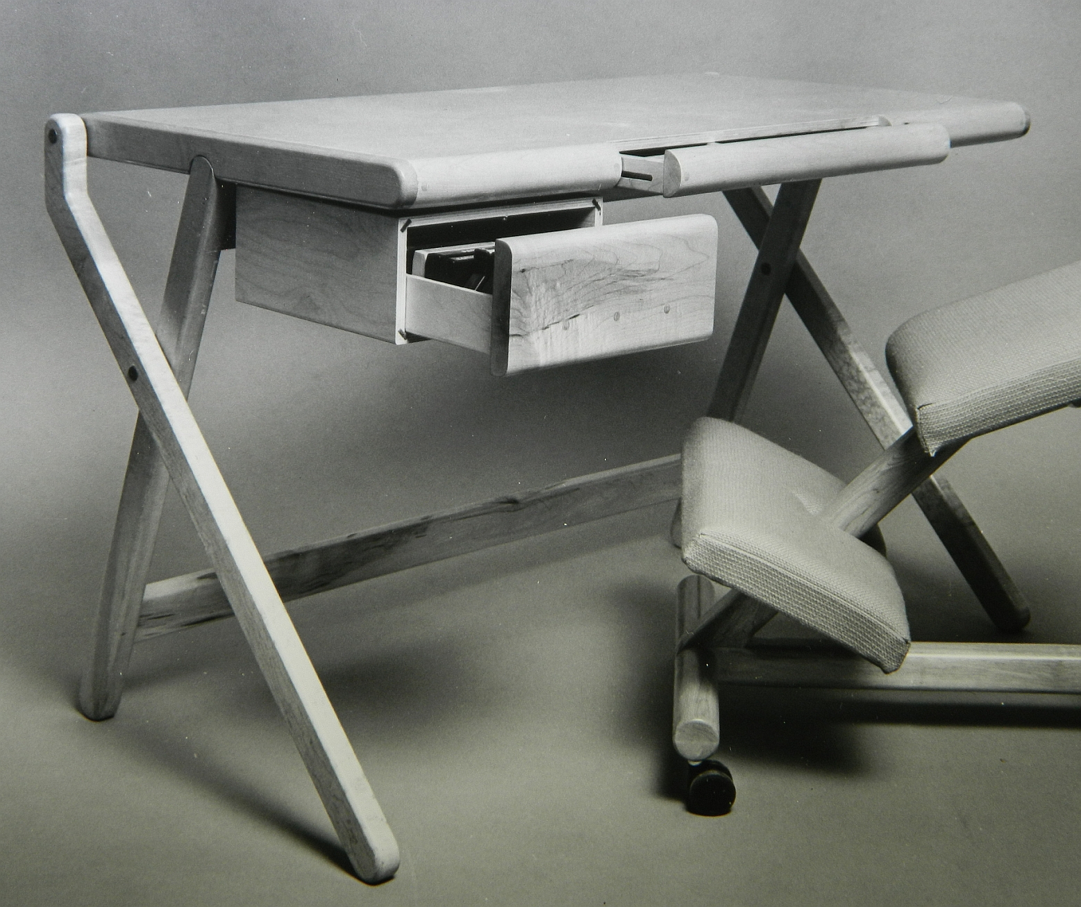
This is my PhDesk. I designed and built it in 1981. This original has a 12mm thick Baltic Birch plywood top, trimmed by 2" wide solid maple sides. The bottom panel is 1/4" thick hardboard. The front and back trim is rounded over to compliment the maple base details. It has a center pencil drawer that can be locked shut when the desk is folded up to carry.  The asymmetric X base folds up easily. The desk is 4" thick when folded flat.

PhDesk with Side Drawer
4" Thick when Folded
It was designed and built when I was a college student and moved several times. I wanted it to fold up so it would be easy to carry and would take up minimum space in the back of my small car. It won 1st place in the case goods category of the 1982 IWF Design Emphasis student furniture design competition. 

Several copies of this design were built for family and friends. My Furniture Design professor liked it enough to make his own copy of it while I was in the workshop making one.  Most have survived including my original prototype.  It was picked up by a furniture manufacturer who thought they could sell it to a line of kitchen accessory stores. They showed me a factory sample made from oak, but never succeeded in selling any.

Oak sample
My original has survived 8 moves so far.  It spent several years as the office desk for a local ophthalmologist. I retrieved it when that office closed.  

It is 24" deep, 29" tall, and 42" wide.  

In Use. TI994A workstation.
One flaw in the original design is that if the front of the desk is lifted the desk may collapse. This "feature" is a source of surprise and consternation for the unsuspecting. Curious spectators are tempted to lift up the front.  That challenge was solved with a strap that attached to the center of the top stretcher and connected to a slot in the underside of the desktop.  The strap is strategically designed to also let the desk fold up. 

My award winning success with the PhDesk, Fit Lounge, and an unfolding Z chair design caught the attention of the university and led to them hiring me to teach the furniture design courses. 

Comments are encouraged!

4D    


Leaning Shelves

These shelves were a quick and dirty project I made sometime before 1988.  With a wobble dado blade on my radial arm saw it was easy to cut slots for all the shelves on the side posts. I cut the slots before rounding over the edges of the posts to reduce any blowout consequences of the dado cuts.

Lean Too?

The shelves are 2' wide and 10" deep. The system is 68" tall. Shelves are 18mm thick Baltic Birch plywood. Two screws through each post side hold each shelf in the dado slots.  The screws are countersunk with my intention to eventually cover them with plugs.  At the time I made these shelves I didn't have a plug cutter so that task was put off and obviously forgotten.  They have been in constant use since being made. My current house has several 2' wide wall sections that these shelves have leaned on over the time I've lived here. 

The advantage of leaning shelves with no back legs is that they don't have to deal with tack strips under carpet edges that make conventional shelves tip forward slightly. When the posts lean against a wall the shelves have a 1/2" gap from the wall.  Great for power cords if needed. 

For Scale
What is kept on the shelves has changed over the years though.  The TI994A PC and cassette player with a tape carousel was my first personal PC.  I won it in a drawing from a Target store opening day celebration in 1980. Learning to program it changed the course of my life.  Programs were saved through a modem to audio cassette tapes. A floppy disk file system came later. I still have this computer and all the accessories/programs. It hides in a box that is hidden somewhere in my house. 

Comments encouraged!

4D

Sunday, August 21, 2022

Parsons Table. A Simple Plywood Table

One of the most frequent inspirations I have for designing and building a project is the presence of scraps of wood left over from a previous project. I use a lot of Baltic birch plywood, and had several roughly 2" wide strips of 12mm plywood left over from a cabinet project.  Those scraps were begging to be made into something useful. 

I appreciate the simple beauty of the classic parson's table. Creating one from wood usually requires careful mitering of pieces and challenging clamping for assembling. There is also an inherent weakness in simple miter jointing.  Strength requires the reinforcement of a splined joint, biscuits , or a locking miter cut done with a special router bit. All of that, to me, is too much work for left over scraps of wood.  A simpler approach was necessary. 

Simple
My plywood table.  Butt-jointed left over plywood scraps, this Parsons table is the end result of my simple approach. 

The strength of this table lies in the interlocking of pieces at each corner of the table.  The beauty lies in how beveling the corners balances each face and eliminates the distraction of the plywood's joint line.  It celebrates the plywood's edge. 

Beveled Outside Corners
This table is 18" square and 20" tall.  The 20" square glass top finishes it off. The green tint of the glass compliments the green color of the base. Four small silicon buttons keep the glass from sliding around. 

Sixteen strips of 12mm plywood were required to make this table.   Eight were 1.53" (38.8mm) wide.  The other eight were 2" (50.8mm) wide.   Glued together the legs and top frame are 2" x 2".  

Top Plane

Top Frame

Legs

I cut a 1/8" deep recess in the top for a piece of 1/8" thick glass to sit flush with the frame top. Before getting a piece cut to fit I realized I had a 20" x 20" piece of glass on hand. The table looked better with that glass sitting atop the base so it won that job. 

This table ended up being a great use for some plywood strips. The top corners have a void and the light colored filler is a 3D printed piece of wood filled PLA, Once I find (or buy some more of) the paint I used for the base I'll touch up the corners to match.   

Questions and comments are encouraged.

4D 

Friday, August 19, 2022

Desk and PC Cabinet. An Ancient Project

 In the years before flat LCD monitors came to be we had boxy analog CRT monitors to view the content of our computers with.  Over the years I designed and made several desks and cabinets to hold the PCs and Monitors and Printers used. Most had some cable management built in. The cables needed then are still the cables needed now and have always been the eyesore that came with PC use. 

When I was in grad school in 1987 I designed this desk/cabinet for myself. It was a challenge to hide away the aesthetically distracting PC parts but make them available when needed.  

Antique Computer Cabinet
This photo is the only surviving evidence of this project. The project was on display at the 1988 IWF Design Emphasis competition where it won first place in the graduate category. The drawer with the PC front showing also holds the keyboard that can be pulled out and placed on the desktop.  The monitor can close up flush with the cabinet face when not needed. A hinging up top door and another door from the side can close down to hide the dot-matrix printer. A shelf below the printer held paper to feed into the printer through a slot above.  

Monitor and printer cables are thoughtfully routed through the hollow left post that supports the upper cabinet. They arrive in the rear of the lower cabinet to plug into a power strip or the rear ports of the PC.  There is a rear panel that pops out to access the rear of the PC and all cable connections.

The desk top and cabinet panels are birch veneered plywood. All edging was hard maple. The desktop is a 5' section from one 8' long piece.  The 3' section left became an alternate top that could replace the long top for a more compact installation. Both used snaps on their end to snap to the cabinet posts. The smaller top didn't need a leg support and would simply cantilever off the cabinet edge.  

The leg post under the desk top was turned on the lathe. It started as three 120 degree sections so tapered slots for the feet could be routed out before being glued together to turn. The feet wedge into these slots and support the post a couple inches off the floor. The post top sockets into a lathe-turned flange screwed into the bottom off the table top. The post with feet could be rotated to point any direction The post and feet come apart easily from the top and each other to make it much simpler to transport. 

The bottom of the posts had wheels attached. With the desk top detached the cabinet could be tipped back and wheeled around. The PC parts inside could remain connected while being moved. A single plug to external power was the only visible cable to deal with. 

This cabinet with the smaller top lived at a sister's home for a few years. It held her computer, monitor, and printer.  When she didn't need it anymore I retrieved it. 

The cabinet was taken apart several years back and the pieces have provided material for other projects.  

I still have the large table top. It replaced the cheap plastic table top of a folding table and has become a project table I can set up when needed in my shop. Legs fold up and the table stores standing flat against a wall. 

Questions and comments are encouraged.

4D