Search This Blog

Friday, June 30, 2023

A Board Stretcher Joint. Just for Fun.

These are renderings from my CNC software of a zipper joint I came up with. A simple way to connect the ends of two boards. Easy to cut using a 3/16" end mill with the boards clamped flat.  This joint could even be used across the center of a table top. For furniture buyers with trouble deciding which woods they want their furniture to made from.  

Mix wood types

Both sides use the same toolpath
Are there schisms between members of your family?  Sport fans who don't agree on the teams they support?  Hardwoods are available in many colors, and two different colors of wood could be used to make a zippered table with both team colors.  

Just for fun. Very possible. 

4D 

Friday, June 23, 2023

Rotary Cut Radius Box Corners

You can cut a rounded corner for a box as a two sided job on your CNC as shown in a previous post:  HERE

You can also cut the rounded corner on the rotary axis of your CNC from the same rectangular starting block. 
16" Long 90 Degree Rounded Corner

What the CNC thinks it is cutting

Actual ends shown in the first image
The centers on the block ends must be a little lower than actual when mounting the block on the radial axis. The profile shape must be placed so all parts of the inner curve can be reached by the bit as it rotates around the center. Very little material is taken off the rectangular block compared to what would need to be removed from a cylinder of wood for the same result. No roughing pass is needed given the small stepover taken by the bit when cutting this shape from a block. For this example I used a 1/4" diameter ball nosed bit. 
Vectors Used
The starting block for a rounded corner with a 1" internal radius and 1.75" external radius is 2.5" wide and 1.0625" thick. Adjust the starting block size to encompass different sizes of rounded corners.  I recommend making the block 2" longer than the final part you need to keep the router/spindle chuck away from the rotary axis chuck and tailstock. 

An example Aspire CRV3D file for this specific project can be found on Vectric's forum here:  Forum.Vectric.com
The actual vector used for the final cut was created with the "Unwraps selected Object" tool you can only access while in a rotary job. 

I helped students with rounded corners for their cabinet projects several times over my teaching career. This is one creative application for the rotary axis of the CNC. 

Question, critiques, and comments are as always encouraged.
4D  

Thursday, June 22, 2023

A Little Pedestal Table

This project was inspired by a thread posted on a woodworking forum about a 3-legged  pedestal table. It was missing a top and had been discarded. It was found and restored with a new top by the woodworker. 

The detailed center post of the table had considerable aesthetic appeal. The 3 legs that dovetailed into it showed a classic way to connect pedestal legs. 

I've had a 3" x 3" block of oak wood mounted on the rotary axis of my CNC for the last 3 months or so.   It was waiting to discover what it wanted to be.  Becoming the center post of a new table seemed to agree with the wood block, so this is where this project started.  The 4th axis toolpaths I cut using my CNC would result in this shape from that block:

Render from Aspire
Actual cut time took a few hours.  The square block had to be reduce to a cylinder. 

First reduce square into a cylinder.
There is a gadget in Aspire that creates a toolpath specifically to remove the corners of square blocks to leave a cylinder. 

From a cylinder, then roughly shaped.
A roughing pass was done to remove most of the waste area from the cylinder. 

Rough cut contours

3/4 done
A final pass with a 1/8" diameter ball nosed bit works its way slowly down the cylinder to produce the final smooth shape. 

Final Shape
Flat areas on the bottom section will be where the feet join into the post. These areas of the bottom section are where dovetail slots were cut.

I flipped the post over end to end so the area where dovetail cuts were needed was at the top (right in the photo) and approachable by the spinning dovetail bit. 

First came pocket clearance cuts done with a 1/4" end mill to remove all the area except where the dovetail undercut would be.  Less work for the dovetail bit to do. 
1/4" end mill set for clearance cuts.

The pocket cut was repeated around the post every 120 degrees. 
Clearance pockets done.

Next came a bit change to a dovetail bit.  This one is 9/16" diameter and has 8 degree sloped sides. 
Setup for a dovetail pass.

The dovetail pass was repeated every 120 degrees around the post.  Once done the post was removed from the rotary axis mount. 
Dovetail cuts done.
With the post done it was time for the legs.  A few sketches of the table with legs were productive. Sketches pointed out that the wood needed to make the legs from needed to be found before the final shape of the legs could be determined.  I had in my scrap bin a couple of oak stretchers left from an abandoned chair design I never finished. They were 3" wide, 1" thick, and 25 inches long. Unfortunately their edges had been rounded over.  I planed them down to 7/8" thick, taking the same amount of wood off of each side. This left about 2.5" of width that was flat in the center of each stretcher.  The leg design I came up with is a simple curve with a hooked foot. Three were cut from that 2.5" width of wood.  

A challenge with the legs was to cut the male dovetail end that would fit into the center post. 
Jigged up for the dovetail cut.
I took care to clamp the first leg so the area for the dovetail was horizontal and sticking up where the router bit could reach it.  I then added supports and stops around it so repeating the cut on the next two legs could use the same setup. 
Dovetail bit zeroed out on the leg top. 
To start the cut I needed to zero the dovetail bit against the left and front edges and the top of the leg. 
 
Dovetail cut.
First dovetail looked centered and correct.  It was time to check if it fit in the post slots.

Fit is good. 
The dovetail slot is tapered to match the tapered shape of this leg end.  The leg slips in easily and snugs up tight.  With a good fit all I needed to do was repeat the cut on two more legs.  With all three cut I could stand up the table base for aesthetic evaluation and detail contemplation. 
Three legs fit. 
The top was yet to come.  I spent a few days contemplating the top.  Final shape. Edge detail?  Inlays maybe?  How the top ends up influences the final details I add to the legs.

Often it takes building an initial design idea to reveal the reality of it compared to renderings on a PC.  That is true for this table. It is a prototype.  A design in progress. The center post was the inspiration for making a table.  Initially the "fancy" post seemed to beg for a fancy top to hold up.  Eventually I realize I was wrong.  

It needed a simple top. Just a nice circle with some subtle detail and curve. My goal was to bring focus to the post.  
Simple round top.
I made this round top to enforce detail continuity.  The legs now stand out as the last parts with minimized relationship to the post.   Below is some iterative playtime with the leg design.

First idea was to taper the leg from top to bottom. Remove some of the visual mass. 

The round top has a subtle elliptical curve on the bottom, and to relate the leg an elliptical taper could be applied.  Perhaps too subtle.
 

A completely new leg profile was tried. A section of an ellipse.

Redirecting the groove to better define the foot.  I may have to make at least one to evaluate how well it adds to the aesthetic composition of the pedestal table. 

The groove on the side of the legs could continue from leg to leg around the section of the post where the legs attach.  Linking the legs specifically to the  post. 
Perimeter groove to continue grooves on legs around the post.

Actual making of that last leg design would present a challenge. It has to be cut from both sides, and the only area around the shape that isn't cut is the back of the dovetail section.  I would need to divide the toolpaths into two sessions, to allow at least two clamps to hold it down.  Cut one side of the edges, then move the clamp to that side before cutting the other side.  Flip the board over and repeat.  Extra effort for a leg that may not be the right leg for this table. 

I used a 3/16" radius round-over bit to soften the round top edge and also the edges of the original legs. My initial instincts to focus on the post and de-focus on the legs and top did the job.  I've concluded it is time to wrap this project up.   The initial legs will do. 
Final less finish.

Some cherry stain on the red oak, followed with a clear finish will match the color of this table to other furniture projects I have in my house.  


Feel free to comment, criticize, or post any questions you may have. 
4D 


Wednesday, May 10, 2023

Two Original 3-Way Corner Joints.

I've seen several versions of 3-way corner joints done in wood by assorted YouTube and woodworker web sites. Other than a double miter cut on all three pieces most require unique cuts on some or all three of the connecting boards. 

I've already come up with one version that can be CNC cut the same on all three pieces, but it required a center block that each piece connected into to complete the assembly. That 4th part cube was more challenging to make than the corner joint cuts were. 

https://4dfurniture.blogspot.com/2016/11/original-cnc-cut-3-way-interlocking.html

This post is my pursuit for unique looking joints that can be cut using a CNC. All three joining pieces must have the same shape done by the same toolpath cuts. 

One potential for a good looking solution is that the details in it may inspire similar details in the rest of the project these corners are used for. A new style perhaps.

The outer corner presents the most significant challenge.  

Pinwheeling around the outer corner each joint line will end up at the inner corners of the connection. This line doesn't need to be direct from outer to inner corner.  A curving line or bumpy line or zig-zag line should also work so long as each side of the line can be cut with the cylindrical or conical bits used by the CNC.  

One example I've made has concave/convex curves on each face as shown here: 


The only flaw in this design is that it leaves a small hidden 3-sided void in the center core.  The curves might encourage some curves in the design the joint was used for.  Perhaps a slight curved taper from the inside corner down to the foot.  One face of the leg might have a convex taper while the other face might have a concave taper. There could even be a shallow arc or bow on the underside of the top rails from leg to leg.  If the table is rectangular then the long sides might have a slight convex bow while the short sides could a slight concave arc. 
Stepped 3-way Miter

Another example is this stepped miter corner joint.  Each piece can be cut with a CNC using the same toolpaths,   Only a little bit of chisel work is needed to take care of two rounded over edges that couldn't be reached by a spinning router bit without messing up another detail of the joint. See the image above.  Each piece ends up with 2 and 2/3 of the 8 cubed volume, leaving the entire volume perfectly filled when assembled.  Cut out and cleaned up, then glued together it is easy to clamp. The flat steps on each piece keep the parts from sliding against each other when clamped down. The stepped joint might encourage a stepped detail to the furniture piece they could be used for. 
Stepped 3-way Miter in Pine
This sample shows a little tear out left by the pocket toolpaths.  It was easy to clamp up. I like the contrast between side grain and face grain on each side, helping the joint line stand out.  

I've got a few more sketched ideas for a corner joint.  I'll need to find some more scraps to see if they'll work and show how well they glue up and actually look.  A good bit of mental exercise this pursuit has been.  Making the toolpaths for the stepped miter corner was the most challenging part. Trying to visualize how the curved version would work before actually making it was a bit beyond me.  I didn't foresee the hidden void left in the core. This proves how valuable it is to make sample prototypes. 

Comments and Questions are encouraged and welcomed.     

4D 

Tuesday, May 9, 2023

Cam Lever Upgrade for my Wen Benchtop Drill Press

Every drill press I've encountered in my life has had the same knurled lever handle that you unscrew to release the table or screw in to lock the table to the post.  Like this one:


While two or three spins of that handle will do the job, there is a better solution out there that takes much less effort to loosen and tighten the table to the post with. 

I've already updated several of my jigs and fences to use cam levers rather then twist knobs.


I did a quick search on Amazon for an M10 Cam Lever and found this one: 


It took a week to arrive, but only a couple minutes to install on my drill press. 

M10 Cam Lever
The powder coated lever is comfortable to handle.  Lift it up to loosen the table.  Put it down to tighten as shown in the photo. There is close to 1/8" of movement of the post collar  gap to go from tight to loose with a simple lift of the cam lever. 

While I'm sure this cam lever was more expensive than the knurled handle that came with the drill, I'd love to see new drill presses come with cam levers.  A far easier to use option.  My Nova Voyager Drill Press was expensive enough that I'm sure such a simple upgrade could have been worked into the price.  A Cam Lever for my Nova is next on my list. 

4D

Tuesday, March 21, 2023

My TaigTool CNC Milling Machine. A new tool and new control software to learn.

When I was a college student I had access to a manual milling machine to cut and shape metal parts with.  My first design job after college was for a company that made residential furniture from metal and glass and occasionally plastic.  I learned several things most don't know about what can be done with metal while working there. 

On February 24th, 2023 I received a mini CNC controlled milling machine that I had ordered.  A tool to permit me to stretch my experience using a CNC to cut wood and plastics toward CNC cutting metals.  A tool to explore with to scratch my design curiosity.  A tool I can use to make more complex parts with metal than I could with that manual milling machine.  

CNC Mini Milling Machine 

Some assembly was required.  Bought from TaigTools.com, this mini milling machine arrived in three separate boxes.  The stepper motors needed to be mounted to each of three axes. The motor and spindle had to be mounted to the Z axis post.  The Z axis post had to be mounted to the X/Y table.  

Once assembled a new adventure began.  To run the CNC it came with Mach3 controller software.  I was able to install it and run the software, but couldn't get it to communicate with the CNC.

The refurbished PC I bought to run the CNC came with a fresh install of Windows 10 Pro, 64 bit version.  As the 64 bit operating system doesn't support parallel ports Mach3 had no communication path to the CNC controller plugged into a parallel port I bought for that PC. 

It took more than a week, but eventually I received the UC100 USB to Parallel adapter that was recommended by the CNC company.  

Initially the adapter also failed to communicate with the CNC controller.  It took some research to find out why the new adapter still wouldn't.   A web clue suggested the PC needed .NET framework for everything to work.  The PC I bought to run the CNC mill apparently didn't have that installed.  Once I had it installed Mach3 did recognize the USB adapter and prompted me to select it from a list of other options. Once I selected it and turned on the CNC controller box I found that I finally did have control of the CNC mill. 

So now begins a new adventure for my retired soul. First task was to add the ability to have the spindle turn on when the job starts and off when it ends. An AC/DC control relay from IOTRELAY.COM along with an 8-pin plug and some 2-lead coated wire did the job.  

Spindle Relay
My next task was wiring up an emergency stop button to the CNC controller. Mounting the stop button where it would be quick to hit was important. I didn't want to make holes in the bench top so a way to clamp it to the edge of the bench was needed. 

Emergency Stop Button

The injection molded ends on the switch body had an angle on them and didn't sit flat on the table top.  I used my Probotix CNC to cut a mounting plate. It allowed for the angled ends and had a slot for the clamp I used to hold it to the bench top with.

Why an emergency stop button?  There have been several moments in the past when what was happening on my Probotix CNC took an unexpected turn. When a cut went awry having a button in reach to slap and stop the router and the movement of the CNC was extremely important.  As I get used to using this CNC milling machine I can loosen the clamp and move this E-Stop button to wherever it will be easiest to reach. 

The next update I am considering is to add limit switches the CNC mill. This should keep the machine from bumping into end stops during a cut which usually ruins the part being cut. That tale I'll reserve for another day. 

Questions and comments are welcome and appreciated.

4D


Monday, March 13, 2023

A Tool Stand for my Taigtool CNC Mini Milling Machine

I've got a new benchtop tool on order and it needs a stand to rest on. There will be associated accessories for this tool so a drawer to keep them in will be useful. The top of the bench has been made and was made from a 25" x 48" x 1.5"thick butcherblock panel purchased from my local Menards.  See here how I made the rectangular panel into a square panel: Square from a Rectangle

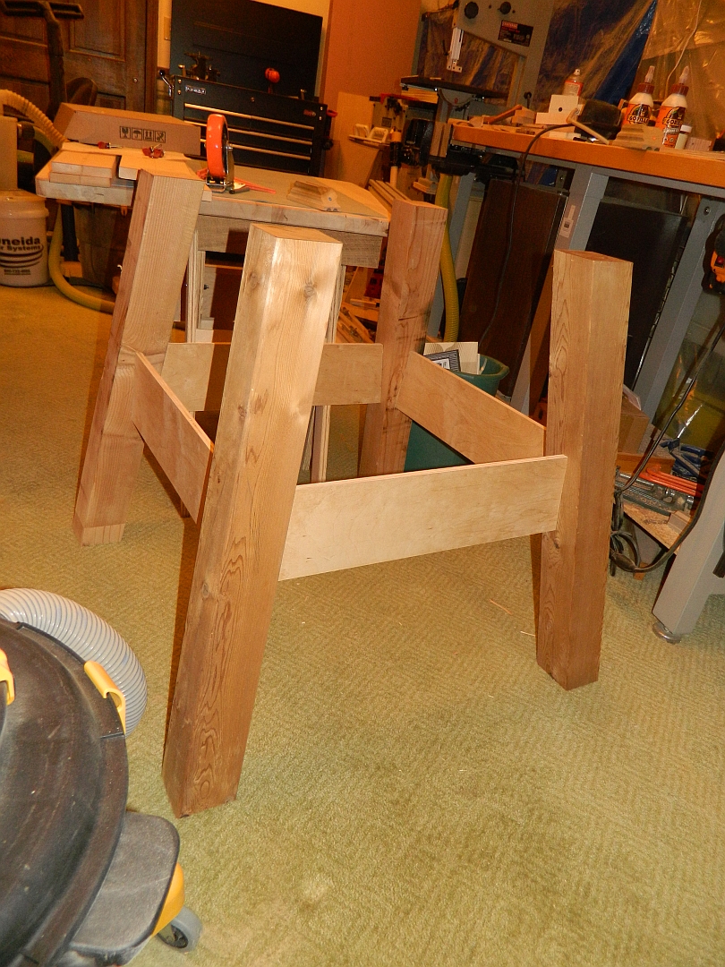
To access the tool without having to bend over the bench will be 38" tall. The legs will be similar to those I made for the prototype bench you can see here: Hobby Bench

Made from 4x4 (3.5" x 3.5") Cedar legs and 12mm x 5.75" plywood stretchers the flared stance should be sturdy and steady when the machine is in motion. 

8 degree legs

The drawer will use 24" long soft closing full extension drawer slides. The stand may eventually have casters.  

I found 6' long 4x4 cedar posts at my local Menards store. Fortunately six feet of material is the longest I can fit in my small car.  Six feet of 4x4 is enough for 2 legs.  I made all 4 legs with very little waste from two 6' long posts.  My Bosch Glide compound miter saw was used to cut the top and bottom compound angle on all 4 legs. 

The tenons on the end of the 12mm thick plywood stretchers were cut on my CNC.  They were clamped vertically in the X plane and held at 8 degrees relative to the Y direction. 

Mortises on two sides of each leg were also cut with the legs on my CNC. They are at an angle to end up vertical in relationship to the angled legs. 

Mortises at 8 degrees

To make the drawer side rails I split a pine board in half and ran both halves though the drum sander until the bandsaw marks were gone. I cut the two pieces in half lengthwise, then glued each half side by side to make two wider boards I can use. A new resaw blade on my bandsaw took awhile to install and set up, but did a nice job of splitting the pine board in half. 

For the two drawer sides I found two 6' long pine 1x3s that would do. I cut them in half lengthwise, then joined one edge on each piece before gluing 2 together x 2 stretchers.  With the glue dry I scraped off any beads of glue, then took all 3 stretcher boards out to my drum sander to clean them all up. They ended up 3/4" thick. 

Next came finalizing the design drawings and verifying the dimensions that all the parts needed to be. 

Drawer rails were made, including the tenons on the back angled end.  Mortises for those tenons were cut on the top inside edge of the two rear legs.  A pocket for the rails has been cut on the side of the two front legs. 

Legs will have their outer corner rounded over by a 1" radius round over bit.  The outer two faces of each legs have been cleaned up and made square to each other on my small jointer. 

Fence for 1" Radius Roundover Cutter
I designed and made a fence for my router table that would work with my 1" radius roundover bit.  I then took all four legs of the base out to my garage shop and ran their outside corner through that 1" radius roundover cutter. The outside corner 1" radius is to match the 1" radius corners of my table top. Some detail continuity to ensure the base leaves no question that it belongs to the table top. After that all legs were sanded to clean up their sides, and a 1/4" radius roundover was cut on the two inner external corners.  

For the drawer I've decided to use finger joints on the corners.   I've already CNC cut the profile for the drawer slides on the two sides of the drawer.  I cut the finger joints on the 4 corners of the drawer box. I used a 12mm router bit to simplify making a slot in the box sides for the 12mm plywood bottom. While I could make a 12mm wide slot with two passes of a 1/4" bit, it simplified the job by having a 12mm bit for that task.  Most 1/2" plywood sold these days is actually 12mm thick.  

 Drawer assembly started with one end (two corners) being glued up.  

24 inch deep drawer.
After the glue was dry on the first end, the other two corners were glued up.   This drawer will slide between two rails that were glued to the base.
These rails will hold the drawer slides for the drawer. 

The articulating "feet" for my parallel clamps helped clamp these parts efficiently. 

Finger joints on the drawer box needed to be flush trimmed to the side contour.  A 1/4" spiral flush trim bit in my hand held Milwaukee router took care of that.  
Finger jointed corners
With the drawer all glued up and finger corners cut flush the drawer was ready to have the drawer slides mounted and fit into the stand. 
Assembled drawer
I applied iron-on birch veneer edge tape to the plywood stretcher edges. When all the parts were done, and rough assembly was complete to verify fit, I took the bench into my utility room to help verify space and association to the PC work station. I might swap these two so the CNC mill will be centered on a wall rather than in a corner. 
I addition to this milling machine I plan to add a metal cutting bandsaw and a metal cutting miter saw to this room.  The bandsaw already has a base.  The miter saw will need a bench to sit on.  I ordered a ready made portable worksite stand for it from Amazon. 

The CNC mini milling machine will arrive soon.  The table top has been handy as I've been working on clearing out more space in this room for other metal processing tools. I need to clear off the table and apply 3 or more coats of finish on it to protect it. 

Assembled the base was a little racked, and the drawer didn't close evenly.  My hopefully temporary fix was a belt clamp between opposite corner legs. 

This table as intended is very stout and firm. When the CNC milling machine arrives I expect it to be happy mounted on this bench. 

Questions and Comments are encouraged and welcome.
4D