Search This Blog

Sunday, April 10, 2022

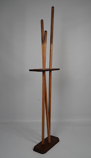
Elliptable. A Table Composed of Ellipses.

Ellipses are simple to draw using most CAD software.  They are also fairly simple to cut out using a CNC.  I designed and made this table before I had a CNC I could use though. It evolved from an idea I had to invert a simple ellipse drawing jig.  To test the jig out I used it to swing the wood panels through a router bit on my router table in elliptical paths. Every ellipse in the design was cut with the same jig.   The legs have a slight rounded edge that echos the ellipse shape of the top above. 

Cherry hardwood


The top came from the center.


Ellipse Jig

The legs join together with dovetails. This design is a good example of detail continuity.

An Ellipse Drawing Jig

Comments welcomed and appreciated.

4D

Wednesday, April 6, 2022

A Simple Finger Joint Jig for the Router Table

This simple jig makes cutting finger joints on box corners fairly simple to set up on a router table.  Variations can be made quickly for fingers of different sizes. 

It uses a piece of 3/8" x 3/8" x 12" long steel key stock, embedded 1/8" deep in a piece of 12mm birch plywood. This provides a guide rail for making the repeated stepped cuts for finger joints.  

Backboard Sled
The backboard sled has a slot cut in the bottom which sets over and slides on the key stock rail.  The center flange of this sled helps keep the sled square and face vertical. Join it to the bottom and face with French dovetails.  It can have a hand hold cut in it and the shape rounded for a more comfortable hold. 
Center Flange with Handle
A 3/8" spiral end mill peeks through a hole in the base which is slightly larger and 3/8" away from the rail.  Clamp the base down to the router table top on two opposite corners. Adjust the bit height to match the thickness of the boards above the base.  To adjust bit spacing from key stock loosen one clamp and bump the base slightly. 
Base with Key Stock Rail. 
To help the jig work smoothly apply some paste wax to the sliding surfaces.

Jigs for smaller or larger fingers can be made using key stock to match the router bit diameter. 1/4" key stock for 1/4" fingers.  1/2" key stock for 1/2" fingers. 

Amazon.com: 3/8" x 3/8" x 12" keystock.


Friday, May 14, 2021

CNC Frame Bridges as an Alternative to T-Track rows or Vacuum Beds.

I previously made a couple of frame bridges to support an assembled student project for some CNC joinery cuts. Lately I've been using the bridges more often to support flat work. They have proven their worth in every case and these are the advantages they offer:

1. They are stiff and flat and remain level to each other and plane-parallel with the CNC's X/Y travel.

2. They have horizontal edges to provide clamping surface for c-clamps to hold the work down.

3. They have aligned holes for pins to set the project board against for perfect alignment with the CNC Y axis. 

4. They attach quickly into the side frame rails with one screw (or cam lever) on each end into a t-nut. 

5. They can be positioned anywhere along the side rails. 


Waiting for cam levers
With cam levers to permit quick positioning


So far two have been enough, but a 3rd will be useful for long boards that may have a bow in them. The 3rd bridge could also be used to clamp a stop block on for repeated identical cuts using the same Y origin. Small C-clamps have been enough to hold work to them, but with a t-slot track embedded in their top any other t-track clamp can be used. 

MDF slats between t-track on another MDF panel that span the CNC frame tend to sag in the middle over time. Plywood bridges in an L or T configuration remain stiff and straight with no deflection under the weight of projects boards or flexing when clamped to warped wood.  With a single t-track on each bridge only 2 or 3 lengths of t-track are needed as opposed to several to cover the bed area.

So far I haven't come across any flat work I couldn't clamp securely down to these bridges.   

My strategy so far for clamping down flat cuts is to use the center of the board as the Home (start/end) point.  Then I make sure the bit won't try and pass though a clamp during cuts. I can offset the start point to the center even if zeroing the bit on the board edges.

I have some thin cork sheets I bought that might be useful as shims to protect the bridges from through-cuts. A 1.5" square to put under boards where each c-clamp ends up should be enough lift to account for router bit penetration. I'll pre-cut a stack of them and keep them stored close to the CNC.  1/8" Baltic Birch plywood scraps can also be used as shims.

I used a self-centering punch to make sure the screws for the t-track would be centered in the screw holes. Their screws go through the top plate and into the top edge of the vertical rib.  
Locking the bridges down doesn't take much time, but does require getting the Philips screwdriver out and putting it away when done. The cam levers are the magic bullet that makes the bridges easy and quick as possible to set in place and use.

Now I'm contemplating how best to accommodate thick/tall work that I could cut if I could sink it down into the frame.  The bridges could be bolted into the bottom slots of the frame to gain 78mm save for the Y-axis limit switches that protrude into the 30mm width of the rails.

The day the cam levers arrived I cut a notch in the top end of the side rails to slip t-track nuts into for them. The levers came with a stud too long but none were available the size I needed. I cut the threaded studs down to the the length needed using my metal cutting chop saw. 

So far I'm happy with this design.  The cam levers make a huge difference in the time it takes to set up for a cut. When I can't use the t-track clamps small C-clamps do a great job of holding down the work. I just have to take care when setting up a job to not run into a clamp.


The black t-track came from Amazon.com:

The cam levers came from Zoro

Comments and questions welcome.
4D

Tuesday, February 25, 2020

A Rare Book Display Stand.


I was asked by our college librarian if I could design and build an original stand she could use to display large rare books on. Once she provided overall dimensions for the stand I set about sketching out a few alternative ideas. 

Initially I wanted to use Northern Hard Ash, but after finding a couple rough Ash boards in the college wood storeroom and planing them flat and clean I discovered they were riddled with bug tracks. My local source for hardwoods would also not sell any Ash for the same reason. 

While I don't usually care for white oak thanks to its busy face grain and color, I bought 26 board feet of it for this project. I ripped it into 1" wide strips and turned them 90 degrees to glue them into quarter grain panels for most of the stand parts. After the glue dried I scraped one side flat before running them through the planer. The resulting planks look beautiful showing medullary rays and far more interesting color variation than the original face grain ever did. 

The Probotix.com CNCs I oversee in the college shop were used to cut the edge and joinery details needed to create the parts and assemble the stand.

The top of this stand is 25" deep by 45" wide. Most parts are made from layered quarter sawn white oak. It is held up by two 3" x 2" posts connected with 4 bowtie tenons through-cut in their top end grain. The tenons are slim waisted which increases the contact area between mortise and tenon, and also resists racking of the joint which can lead to loosening.
Shelf for cotton gloves
As this is a stand for books I added a couple of famous quotes about books/reading on the visible faces of the two stretchers. The librarian also requested that the stand would have a shelf to keep a box of cotton gloves on.


I could find no better words than these about the value of reading.


You can see the varied grain patterns in the top.


The design is a result of my pursuit for simplicity in structure.


The 2 columns of 4 bowtie tenons are end grain of the posts peeking through the top.

Photos above were taken in the finish room of the fabrication lab where I taught. They were taken right before I delivered the stand to the college library.
Installed in the college library rare book room.

The stand is displaying rare drawings created by Frank Lloyd Wright. 
Standing in the college library rare books room entrance window. Seaton Hall, KSU.
4D


Wednesday, June 13, 2018

A Simple Box, with Four Different Corner Joints.

This is an assignment sample I made for our beginning Workshop One class.  I designed it to show the students different ways to connect wood at a right angle.  All the joints on this example were cut using my CNC.  Simpler versions of each corner joint can be done using more conventional tools in a woodworking shop.  To show them what a CNC can do if they think out-of-the-box each corner has a feature that would be very difficult to do with conventional tools.

Miter.  The conventional way to reinforce a miter joint would be to use a spline or biscuits to cross between the two halves.  Using my CNC I've made a hidden alternating mortise and tenon row that disappears inside when the joint is closed. Much easier to glue up as this joint won't slide in any direction when clamped.


Tongue and Groove.  Normally a simple tongue in a simple groove is enough to make a good corner joint.   Using the CNC I've added a row of 5 small through-tenons that center the joint and add some aesthetic detail to this corner.


Box Joint. The CNC enhancement for this row of fingers was to make them each a different progressively larger width.  Tough to do using any other jig or tool, but fairly easy to draw up for the CNC to cut them.

Shallow Rabbet.  Conventionally we would reinforced this with screws covered by wood plugs.  Using the CNC I simply cut 3 round tenons from the end grain of the short side to replace the screws and plugs.   The end look is the same. The tenons align the joint.


The bottom is 1/4" (6mm) Baltic Birch plywood.  Rather than install it near one edge of the box, I'11 put it 1/3 of the way up from one end.  This will divide the box into two compartments with one twice as deep as the other.   Flip the box to access each.  The lids won't open unless they are on top. Twisting latches slide into the lid to keep it in place when it is on the bottom. A shallow perimeter rabbet on each lid aligns it to the box. When on top just twist the latches then the top can be lifted out.

4D

Monday, July 3, 2017

Dowel Splice Joint

I've got a closet in my spare bedroom (storage room) that I wanted to add another clothes hanger rod to.  Among my scrap pieces I had two 1.25" diameter closet rod sections that together would be long enough, but neither was long enough on their own.  The distance to span was roughly 22". 

This is a CNC-cut splice joint I came up with to solve the problem.   My test cut done on smaller scraps is shown in the photos.  I'm calling it my radial finger joint.


The finished spliced rod is now loaded with clothes and is handling the weight with no complaint.

To hold the dowels on my CNC I used my adjustable angle clamping jig set to vertical with a vertical scrap of plywood clamped to it.  The dowels were trapped/clamped against the jig and edge.

One application of this joint was for a student of mine's project.  Walnut dowel extensions to oak dowels.  A coat rack with key tray and umbrella hook, By Ellie Williams:

4D 

Saturday, December 31, 2016

Low Profile CNC Table Vise

I often need a way to clamp small parts on my CNC bed without using clamps that hold them down from the top.  In the past I've been able to use a manufactured vise borrowed from my drill press table, but it is rather tall and my CNC doesn't have a lot of Z axis clearance.

This prompted me to come up with this low profile vise:


All the wood parts were cut out on my CNC from 1/2" (12mm) and 3/4" (18mm) baltic birch plywood. The bottom plate that holds the moving jaw down is from a scrap of old 3/16" thick plywood.   Follow-up procedures included drilling pilot holes for screws that hold the main parts together, and tapping threads in a drilled out 5/16" hole for the 3/8" x 16tpi threaded rod I used.

I've added some 100 grit sandpaper to the jaw clamp faces for more friction than the plywood edge itself has.  In use it now holds anything tight enough that when being cut by the CNC it doesn't move. The four bolt holes were spaced to align with the t-track slots in the bed of my CNC.  At the moment I use a box end wrench to turn the end where two nuts are jammed together.  I embedded a vertical steel post in the moving jaw for the threaded rod to push against.  It also helps keep the plywood from splitting.   Brass screws were used to hold all the parts together, as well as to keep the individual plywood parts from splitting.  The CNC will just mill through the brass screws should it accidentally encounter them.

I've posted a file that includes all the vectors I used in .CRV (Vectric's VCarve) format on their forum site:  http://forum.vectric.com/viewtopic.php?f=2&t=24361#p189439.  Direct download link: http://forum.vectric.com/download/file.php?id=53303

If you are interested in making your own feel free to use my file as is or modify it to fit your CNC's bed mounting/clamping system.   I know I'll get considerable use out of mine.

The software I used to cut the parts out is Aspire from Vectric.com.  Aspire is their most expensive and full featured product, but they do have lower priced options that would have been fine for drawing up and cutting out this project.

Speaking about Aspire, it was recently upgraded to version 9.  Version 9 has enhanced drafting features, and a much improved rendering engine to show how your parts should look after being cut.  below are two images of the base plate of the vise, all done in one file and once rendering.  The new and most appreciated feature is being able to show what 2-sided cuts would look like together.
Bottom side.

Top side.
4D

2/18/2018 - Update for the bed vise:   I've taken it apart and re-assembled it so there is no more conflict with the hold-down bolts.   I also CNC'ed a slot for a 3/8"-16tpi square nut and the nut slid in there tight.   I drilled out the wood threads and now am confident the vise won't strip out in use. Steel threaded rod through a steel nut now.   I found that square 3/8"-16 tpi nut in a coffee can full of assorted hardware living in my garage shop.  Now it has a home.